Download
1 / 21
210 likes | 347 Views
Real robots:. “Phoenix-3”. Virtual robots:. SOFA-2009 Virtual robot benchmark model. 2006 - 2007. 2007 - 2008. 2008 - 2009. Mobile robots SOFA-2009 and “Phoenix-3”. Alex Astapkovitch, head of the Student Design Centre State University of Aerospace Instrumentation

E N D
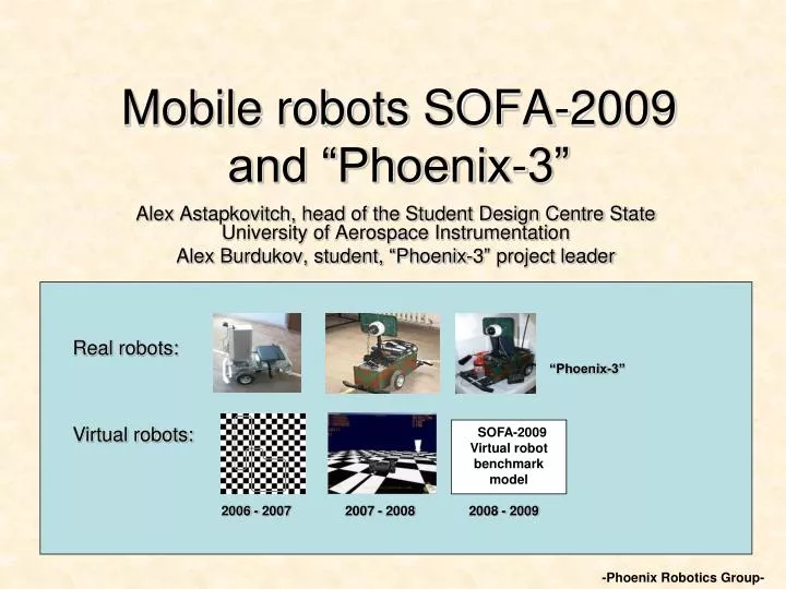
Real robots: “Phoenix-3” Virtual robots: SOFA-2009 Virtual robot benchmark model 2006 - 2007 2007 - 2008 2008 - 2009 Mobile robots SOFA-2009 and “Phoenix-3” Alex Astapkovitch, head of the Student Design Centre State University of Aerospace Instrumentation Alex Burdukov, student, “Phoenix-3” project leader -Phoenix Robotics Group-
It is a free ticket on fast train for young researches to Computational Robotics field valley ! Virtual robot SOFA-2009 - Mobile robots are complex electromechanical devices the real experiments are very expensive in sense of time and stuff. - During Phoenix-2 project a virtual environment and simplified robot model were developed to generate on board cameras images. - Phoenix-3 project is the third step of Phoenix student research group that consists from the hardware development and the background theory activities. - The strategic goal of the “Phoenix-X” projects is a developing of understanding of the learning strategy for the control system on base of a neuron net. - SOFA-2009 was started as scientific support for “Phoenix-3” project and still is the part of “Phoenix-X” student research activity, but now...
Virtual robot SOFA-2009 Research activities of Phoenix research group is concerned of “Teaching by Showing” approach for multi channel real time control systems, based on artificial neural net. -Main goal of SOFA is introduction to robotic society the benchmark model than can be used to investigate neuron net control system learning. SOFA-2009 benchmark model formulated as system of ordinary differentional equations: dx/tx =f(x)+U(t) X(0)=X0 -The model has to be as simple as possible and of autonomous differential drive wheel robot is used as legend. -MathCAD 14 was used as a tool due to friendly and fast user interface.
Kinematics and dynamics models of virtual robot SOFA direction “forward” axe y φ(t) – robot angle position axe x R(t) – instant rotation radius Rс (t)– robot center position vector R0 (t) - instant center of arc axe x earth fixed frame Virtual robot SOFA-2009 φ (t+∆t)- φ (t) = ∆ φ (for left wheel) = ∆ φ (for right wheel) R0 (t) = R0 (t+∆t) Basic relations:
Virtual robot SOFA-2009 Model includes dynamic equations, gear model for every wheel, motor model, control system model. Model SOFA-2009 is defined with parameters set : Dw = 0.3 Lr = 0.5 Jr = 0.25 k11 = k22 = 75 k12 = k21 = 10 Rm = 0.1 Lm = 0.01 k13 = k23 = 1.5 Vmax = 12 Vmax is the maximal absolute value for accumulator voltage. The simplest as possible model consists of 7 ODE with at least 9 parameters.
Virtual robot SOFA-2009 SOFA-2009 model testing Rc(0)X,Y = 0 φ(0) = 0 Control voltages: U1(t) = U2(t) = Umax = 12 V. TEST_1. Moving forward with speed 4/5 m/sec Control voltages: U1(t) =0 U2(t) = Umax = 12 V. TEST_2. Rotation around left wheel with ang. speed π/4 r/s
Left motor control channel Wleft = [w0l,w1l,w2l] Sensor layer Uin left Uin right AFSS Right motor control channel Wright = [w0r,w1r,w2r] Transfer function APS – Angle Position Sensor ASS – Angle Speed Sensor AFSS – Angle Final Speed Sensor Actor layer neuron Vmax, Vmin APS ASS Uout Left Motor Uout Right Motor Vout Vin Virtual robot SOFA-2009 Example of neuron control system:
S1(T1) S2(T1) .. Sn(T1) S1(T2) S2(T2) .. Sn(T2) …………………… S1(Tp) S2(Tp) .. Sn(Tp) w1 w2 wn A1(T1) A1(T2) A1(Tp) = * S * w = Ua Matrix form min F(w) = (Sw - Ua, Sw – Ua) + (w,w) w Tixonov regularization w = (ST S + E) –1 ST Ua Weights calculation Virtual robot SOFA-2009 One step learning paradigm idea:
1. SAMPLE GENERATING AND NEURON NET LEARNING Robot model Cauchy problem solution for [T0 -T1] Initial position vector X0 Control voltage matrix (vector Ua(t) for every motor ), that corresponds to robot mission SOLUTION TABLE [ti, X (ti) ] NEURON NET CONTROL SYSTEM STRUCTURE Final position vector X(T1), velocity vector V(T1) Sensor System Model Weight Matrix Calculation W= (StS+γE) -1St Ua Virtual robot SOFA-2009 • Experiment with virtual robot includes at least three steps: • sample generating and neuron net control system learning ; • simulation of the robot dynamics with "learned "neuron net control system; • research experiments.
Initial position NEURON NET CONTROL SYSTEM MODEL Cauchy problem solution and estimation Robot model Final position NEURON NET CONTROL SYSTEM MODEL Cauchy Problem Solution Initial and final positions, control net structure depends on research PROBLEM POST PROCCESINGS Virtual robot SOFA-2009 2. CONTROL SIMULATION 3. NUMERICAL EXPERIMENTS Examples are presented in applications to articles and in site http://guap.ru/guap/sdc
Sample rotation to left with maximal velocity learning sample of control voltages for left and right motors preliminary estimation of the training estimation of the robot dynamics under neuron net control system for π/4 rotate to left for limited and unlimited actor voltage Virtual robot SOFA-2009 • Example of the supervised learning for π/4 rotate to left sample:
Virtual robot SOFA-2009 Sample of autonomous operation for π rotate task: rotation to left on π with limited and unlimited Vmax motor currents for limited and unlimited voltage phase portrait for unlimited case: start point (0,0),final (3.14,0) phase portrait for limited Vmax: start point (0,0),final (3.14,0)
Virtual robot SOFA-2009 • MathCAD 14 example code presented in article as appendix to articles • A. Astapcovitch “Virtual mobile robot SOFA-2009 for Computational • Robotics Research”; • A. Burdikov “Autonomous Robot “PHOENIX-3”” - Virtual robot SOFA-2009 with neural net control system and learning procedure can be downloaded for free from the site http://guap.ru/guap/sdc - Site section SOFA-2009 has examples: SOFA 2009_TEST1_2.xmcd - SOFA model test SOFA 2009_A_LEARNING.xmcd - learning to rotate SOFA 2009_DISTANCE_LEARNING.xmcd - learning to move ahead SOFA 2009_AD_LEARNING.xmcd - learning to reach the prescribed 2D point
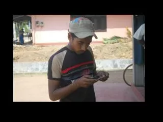
Autonomous Robot “PHOENIX-3” Project legend: Autonomic robot Phoenix-3 is designing to be able to patrol the determined area with the purpose of detection the centers of the flame. In case of the flame detection the robot should come nearer and use the onboard fire extinguisher to eliminate flaming. For orientation the video shock-proof camera with the rotary mechanism and a zoom lens is supposed to be used.
Autonomous Robot “PHOENIX-3” • There are several steps in neural system synthesis using “teaching by showing” methodology. - During the 1st step robot’s movement are controlled by a traditional control system or by operator. During this procedure robot’s sensors information and control commands are written to onboard laptop. -This data is used on the 2nd step for neural regulator coefficients determination. - It means that the control system has to have at least two basic modes of operations: operator control mode and autonomous operation. - Operator control mode is used during the learning phase.
Rotating camera (sensor) Still Camera Multichannel Video IP-codec ASK-Lab Ethernet Laptop RS-485 RS-232 CANbus Ultrasonic Orientation System Controller ASK-Lab Sensors Rotating camera (position motors) Left and Right Motor Control Bridges Fire extinguisher engine Actors Autonomous Robot “PHOENIX-3” Control system structure during autonomous operation:
Video link Computer Wi-Fi AP cam. output 1 cam. output 2 Radio link Operator Pad 1 (robot) RF-transmitter Pad 2 (fire extinguisher) Autonomous Robot “PHOENIX-3” Control system structure for operator control mode: -During Phoenix-2 experiments, two control schemes were tested – one with analog and one with digital control channel. -It was noticed, that digital control system has significant delays in the channel, so it was decided to use an analog control system for Phoenix-3 project.
Analog joysticks Laptop RF-transmitter RF-receiver Controller Actors and sensors Autonomous Robot “PHOENIX-3” Two channel RF-control system. -Phoenix-3 project implements two channel control system: one for robot movement control and another for control on board equipment. -Hitec FOCUS 6 RC-equipment was used during experiments. It includes a control pad and receiver module.
CANbus module structure: 5 1 2 3 5 6 4 6 7 8 Autonomous Robot “PHOENIX-3” Ultrasonic Orientation System. Has a net structure based on CANbus. 1 – MCP 2510 CANbus controller chip; 2 – PIC18F458 microcontroller chip; 3 – 16-bit counter; 4 – ultrasonic pulses generator; 5 – ultrasonic receiver; 6 – ultrasonic transmitter; 7 – frequency divider; 8 – quartz generator. - Ultrasonic distance measuring module based on MuRata MA40S8S and MA40S8R devices was developed. - Developed module can measure of distances up to to 2 m. with accuracy resolution approx. 0,2 mm.
Algorithm of using fixed inclination angle: S1 S2 SN This column is filed by “hand ” with camera inclination angle value specific for every learning sample SI. SEN= Autonomous Robot “PHOENIX-3” Video subsystem. It was demonstrated during Phoenix-1 project that camera inclination sensor is the necessary element of control system. “Phoenix-3” video subsystem of the robot includes a rotary shock-proof camera with the rotary mechanism, a zoom lens and a two-channel video digitizing module with an Ethernet interface.
Autonomous Robot “PHOENIX-3” • More info about project “Phoenix-3” can be find on the site http://guap.ru/guap/sdc