Download
1 / 3
30 likes | 146 Views
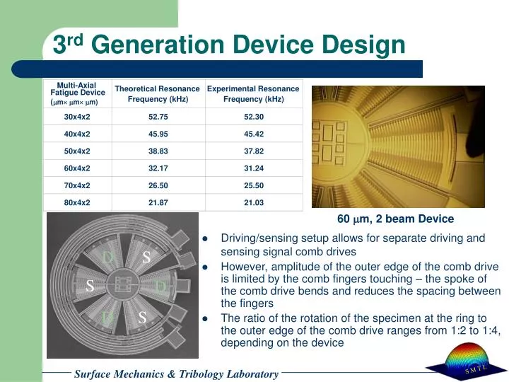
Multi-Axial. Theoretical Resonance. Experimental Resonance. Fatigue Device ( m m m). Frequency (kHz). Frequency (kHz). 30x4x2. 52.75. 52.30. 40x4x2. 45.95. 45.42. 50x4x2. 38.83. 37.82. 60x4x2. 32.17. 31.24. 70x4x2. 26.50. 25.50. S. D. 80x4x2. 21.87. 21.03. S. D. D.

E N D
Multi-Axial Theoretical Resonance Experimental Resonance Fatigue Device(m m m) Frequency (kHz) Frequency (kHz) 30x4x2 52.75 52.30 40x4x2 45.95 45.42 50x4x2 38.83 37.82 60x4x2 32.17 31.24 70x4x2 26.50 25.50 S D 80x4x2 21.87 21.03 S D D S 3rd Generation Device Design 60 mm, 2 beam Device • Driving/sensing setup allows for separate driving and sensing signal comb drives • However, amplitude of the outer edge of the comb drive is limited by the comb fingers touching – the spoke of the comb drive bends and reduces the spacing between the fingers • The ratio of the rotation of the specimen at the ring to the outer edge of the comb drive ranges from 1:2 to 1:4, depending on the device
Multi-Axial Est. Max von Mises Fatigue Device (m m m) Equivalent Stress (GPa) 30x4x2 0.65 40x4x2 0.72 50x4x2 0.73 60x4x2 0.68 70x4x2 0.60 80x4x2 0.51 Experimental Resonance Frequency Multi-Axial Unnotched Notched Fatigue Device (kHz) (kHz) (m m m) 30x4x2 52.30 ~46 40x4x2 45.42 ~40 50x4x2 38.83 ~29 60x4x2 31.24 ~29 3rd Generation Maximum Stress • These values for stress are based on the maximum deflection obtainable in vacuum – estimating an amplitude of 2 mm at the end of the specimen • The devices were run for >1010 cycles and no fatigue damage was observed • To increase the maximum stress and produce failure, an notch was introduced by FIB • The stress concentration factor ranged from 3 - 4 • Stresses ranged from ~ 1 to 4 GPa • The introduction of the notch reduced the stiffness and therefore resonance frequency of the device Area notched with FIB MUMPS 48 Chip 5 60-mm Beam Device
Multi-Axial Theoretical Resonance Experimental Resonance Fatigue Device (m m m) Frequency (kHz) Frequency (kHz) 30x4x2 92.30 83.29 40x4x2 60.72 54.00 50x4x2 42.33 37.50 60x4x2 30.91 27.33 40x5x2 81.13 71.37 4th Generation Device Design • Design now has a stiffer comb drive-ring structure • The ratio of the rotation of the specimen at the ring to the outer edge of the comb drive is a little less than 1 • More linear amplitude of comb drive along the spoke • Allows for a 2 mm displacement at the end of the specimen beam • Can therefore reach stress levels high enough to cause failure