Download
1 / 24
240 likes | 470 Views
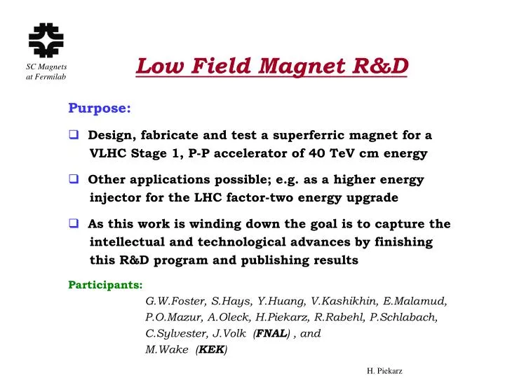
Low Field Magnet R&D . Purpose: Design, fabricate and test a superferric magnet for a VLHC Stage 1, P-P accelerator of 40 TeV cm energy Other applications possible; e.g. as a higher energy injector for the LHC factor-two energy upgrade

E N D
Low Field Magnet R&D Purpose: Design, fabricate and test a superferric magnet for a VLHC Stage 1, P-P accelerator of 40 TeV cm energy Other applications possible; e.g. as a higher energy injector for the LHC factor-two energy upgrade As this work is winding down the goal is to capture the intellectual and technological advances by finishing this R&D program and publishing results Participants: G.W.Foster, S.Hays, Y.Huang, V.Kashikhin, E.Malamud, P.O.Mazur, A.Oleck, H.Piekarz, R.Rabehl, P.Schlabach, C.Sylvester, J.Volk (FNAL) , and M.Wake (KEK)
Intellectual and Technological AdvancesResulting from the Superferric Magnet R&D • Magnet assembly and welding technique • 100 kA dc power supply • 100 kA dc power leads • Operation of a superferric magnet model • Magnetic measurements for a small bore • Accelerator quality magnetic measurements DOE Review of Fermilab SC Magnet Program
Basic Features of the Magnet • Combined function gradient dipole • 2-in-1 warm iron yoke • 2 Tesla bend field • 20 mm pole gap • Alternating gradient 65m (half-dipole length) • Single-turn 100 kA transmission line conductor • Operating temperature up to 6.5 K • Warm beam pipe vacuum system DOE Review of Fermilab SC Magnet Program
Lamination Design Study Slots Top Pole Bottom Pole • Use of slots in poles helps to reduce saturation sextupole defect and gradient shift • Results from a water cooled magnet model showed that overall B-field stability is +/- 0.02 % within the 20 mm pole gap • The slides show that the field shape did not change between 1.25 T and 1.8 T DOE Review of Fermilab SC Magnet Program
Test Magnets Half-Cores • Test magnet half-cores of 1.5 m, 3 m and 6 m length are being fabricated at the Efremov Inst., St. Petersburg, Russia • The laminations are produced using high precision die and assembled into half-cores with tolerances < 0.02 mm • Expected delivery to Fermilab in July, 2002 Top and bottom half-cores DOE Review of Fermilab SC Magnet Program
Transmission Line Conductor R&D • All conductor types to be used for the superferric magnet were successfully tested in our Superconductor Test Facility in MW9. A magnetic field from a dipole magnet generated up to 100 kA current in the superconducting loop DOE Review of Fermilab SC Magnet Program
Transmission Line Conductor R&D • All conductor lines use invar tubing for cryopipes to minimize shrinkage • Conductor properties: - Drive bus - Braid of 288 SSC outer dipole strands - 100 kA current @ 1 Tesla at 6.5K - LHe channel 25.3 mm dia. - Return bus - As above, except for the increase of the LHe channel dia. to 36.8 mm in order to minimize the pressure drop - Corrector space conductors - 9 Rutherford cables (270 SSC inner dipole strands) - 100 kA current @ 1.5 Tesla at 7 K allows to place drive and return buses at ~5cm of each other DOE Review of Fermilab SC Magnet Program
Transmission Line Conductor R&D • Conductor assembly • Swaging technique (pulling a series of carbide steel balls through the LHe channel) was successfully used to fix conductor firmly inside the cryo-pipe and thus greatly simplifying the assembly process • Status - All components exist to assemble up to 100 m of a drive conductor - In all upcoming tests the drive conductor will also be used as a return bus - All bent conductor sections will be made of assembly of 9 SSC inner dipole cables ( all components exist, assembly in progress ) Assembly of a 6 m long transmission line conductor DOE Review of Fermilab SC Magnet Program
Transmission Line Conductor R&D • Conductor splicing techniques • Used aluminum block heaters with large compression force on the splice - Spliced conductors: ( i) 9 to 9 Rutherford cables, 30 cm length, 3.6 kW power (ii) Braid to 8 Rutherford cables 10 cm length, 1.2 kW power - Splice resistance: Less than 0.02 nOhm ( limit of the measurements ) - Power dissipation at 100 kA Less than 0.2 W per splice ( limit of the measurements ) DOE Review of Fermilab SC Magnet Program
Magnet Assembly Technique R&D • Will use laser technology to weld connecting plates between half-cores • Laser welding reduces the heat affected area by a factor of ~100 with respect to TIG welds • Welding sequence: 1. Weld split connecting plates to half-cores 2. Weld connecting plates together through slots in the spacer bar • A “key” in the connecting plates prevents spill of the molten steel onto the cryostat wall DOE Review of Fermilab SC Magnet Program
Magnet Assembly Technique R&D • Preset press on the half-cores assembly ~5 T/m • Expected tension after welding >> 10 T/m • Preset press on the conductor cryostat ~ 200 kG/m • Cold pipe supports made of “ultem” (large cost reduction) – expected shrinkage ~ 0.1 mm/peg • A preset press of ~200 kG/m compensates for shrinkage of pegs Cold Pipe Supports & Shield Welding & Press Fixture Spacer Bar Conductor Cryostat Conductor & He Channel Connecting Plates DOE Review of Fermilab SC Magnet Program
Magnet Assembly Technique R&D Laser beam will move between press posts (skip welding mode) and then weld connecting plates through the slots in the spacer bar. Lamination damage due to laser generated heat was successfully tested. The forthcoming test is to determine tension after laser weld. • A 3.5 kW laser mounted on a 4m long gantry at Laser Mach. Inc., Somerset, WI that will be used for welding our magnets. • The YAG or CO2 laser will make 3 mm deep welds at a speed up to 4 cm/s with positioning precision down to ~10 microns Laser Head Gantry DOE Review of Fermilab SC Magnet Program
Magnet Test Arrangement • In order to test the VLHC superferric magnets at Fermilab we had to design and build both the 100 kA power supply and the 100 kA power leads DOE Review of Fermilab SC Magnet Program
100 kA DC Power Supply R&D • Rectifier cells 400 V x 60 A 1.5 V x 10 kA • 15 cells assembled and individually tested • 10 cells successfully tested in a parallel operation at 100 kA • A B-field regulation system was successfully tested • Work in progress on better than E^(-4) regulation DOE Review of Fermilab SC Magnet Program
100 kA Power Leads R&D • Design complete • 208 Cu 1.65m long, 6 mm dia rods/lead • Horizontal LHe flow (anodized Al baffles force flow up/down along the lead) • LHe consumption: - 3 g/s standby - 6 g/s at 100 kA DOE Review of Fermilab SC Magnet Program
100 kA Power Leads R&D • Performance projection • Optimized for 90 kA, a nominal current of the VLHC magnet • At 100 kA unstable with LHe flow < 5.6 g/s • The resistance of the solder joint of the rods at the cold end is the key factor to keep LHe flow at the projected level. Based on preliminary tests and analysis we predict that this resistance in both leads will be in a nano-ohm range at LHe temperature, thus being very satisfactory. DOE Review of Fermilab SC Magnet Program
100 kA Power Leads R&D • Assembly of a current lead required simultaneous soldering of 202 copper rods to both warm and cold ends as well as soldering of 9 SC cables to the cold end. It was done by heating-up the whole assembly to 400 F in IB2 oven. A close-up view of SC cables and Cu rods soldered to the cold end of the current lead DOE Review of Fermilab SC Magnet Program
Cryogenic System for Magnet Tests • Two 500 l dewar LHe supply system. A cryobox (used in MW9 tests) allows to swap dewars during system cool-downs. DOE Review of Fermilab SC Magnet Program
Cryogenic System for Magnet Tests R&d • Cryogenic electrical insulators (new compared to MW9 system) • Sizes from 0.25” dia. (Instr.) to 3” dia. (Lead’s GHe exit) • All insulators developed and fabricated at MTF Products: - Ceramics with invar sleeves - 6 kV breakdown voltage (3 kV expected for VLHC) • Bellows are installed above and below the insulators to protect ceramics to invar tube joints during cooldown and warmup processes A part of the Instrumentation Tower design Insulator Bellows DOE Review of Fermilab SC Magnet Program
Magnetic Measurements R&D • Multi Hall Probe Station • Fabricated at Efremov Inst., St. Petersburg, Russia - 50 elements ( in each beam gap ) arranged in 3 planes to facilitate measurement of higher harmonics - Laser tracking system for the station position on the magnet - Radio-wave communication for transferring data • Hall Probe Station tests are in progress at MS6 Laser Receptor Hall Probe Holder and Carriage, (same is on the opposite side) Pole Gap Structure imitating Magnet DOE Review of Fermilab SC Magnet Program
Magnetic Measurements R&D • Will use tangential coilsto measure higher harmonics of the B-field • Coil parameters: - Length 3m & 6m - Opening angle 15 deg - Number of turns 20 • Preliminary design and cost estimate done Neoprone Elastoner Springs Vespel SP-211 Probes Vespel Sleeve Bearing Nylatron GS DOE Review of Fermilab SC Magnet Program
Schedule and Manpower • FY 2002 schedule • Assemble test system in MS6 • Commission 100 kA power supply • Commission 100 kA power leads • Assemble and install 1.5m magnet • Test system and magnet operations • Measure magnetic field quality using multi-Hall probe station • Complete design of MS6 to MW8 conductor transfer lines and make final design of tangential coils • FY 2002 manpower • 1 FTE Scientist • 1.5 FTE Engineer • 1 FTE Technician MW8 TUNNEL MS6 ENCLOSURE DOE Review of Fermilab SC Magnet Program
Schedule and Manpower MS6 Enclosure MW8 Enclosure • FY 2003 schedule • Install MS6 to MW8 conductor transfer lines (~10 m length) • Assemble and install in MW8 the 3m and 6m magnets • Fabricate tangential coils • Test new magnets operation • Perform B-field measurements using tangential coils • Publish results • Secure MS6 and MW8 for possible future superferric magnet studies • FY 2003 manpower • 0.1 FTE Scientist • 0.3 FTE Engineer • 1 FTE Technician Conductor transfer line to be assembled in FY 2003 DOE Review of Fermilab SC Magnet Program
Summary and Conclusions • Design and fabrication of all major components (magnets, power leads and power supply) is nearly complete and the test system with 1.5 m magnet will be assembled and commissioned in FY 2002 • The 3m and 6m magnets (together with the tangential coil magnetic measurement system) will be assembled and installed in MW8 in the first half of FY 2003 • The accelerator quality magnetic measurements of the VLHC superferric magnets will conclude in FY 2003 • With rather small effort in FY 2003 the intellectual and technological advances resulting from nearly 4 years of the superferric magnet R&D will be captured and available for publication DOE Review of Fermilab SC Magnet Program