Download
1 / 18
180 likes | 396 Views
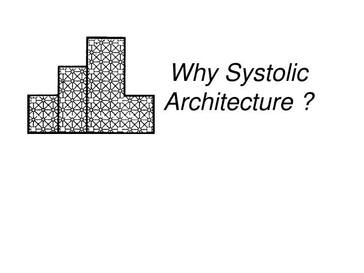
Why Systolic Architecture ?. Motivation & Introduction. We need a high-performance , special-purpose computer system to meet specific application. I/O and computation imbalance is a notable problem. The concept of Systolic architecture can map high-level

E N D
Motivation & Introduction • We need a high-performance , special-purpose computer • system to meet specific application. • I/O and computation imbalance is a notable problem. • The concept of Systolic architecture can map high-level • computation into hardware structures. • Systolic system works like an automobile assembly line. • Systolic system is easy to implement because of its • regularity and easy to reconfigure. • Systolic architecture can result in cost-effective , high- • performance special-purpose systems for a wide range • of problems.
Key architectural issues in designing special-purpose systems • Simple and regular design • Simple, regular design yields cost-effective special • systems. • Concurrency and communication • Design algorithm to support high concurrency and • meantime to employ only simple. • Balancing computation with I/O • A special-purpose system should be match a variety • of I/O bandwidth.
Basic principle of systolic architecture • Systolic system consists of a set interconnected • cells , each capable of performing some simple • operation. • Systolic approach can speed up a compute-bound • computation in a relatively simple and inexpensive • manner. • A systolic array in particular , is illustrated in next • page. (we achieve higher computation throughput • without increasing memory bandwidth)
CONVOLUTION In mathematics and, in particular, functional analysis, convolution is a mathematical operator which takes two functions f and g and produces a third function that, in a sense, represents the amount of overlap between f and a reversed and translated version of g. Typically, one of the functions is taken to be a fixed filter impulse response, and is known as a kernel. Such a convolution is a kind of generalized moving average, as one can see by taking the kernel to be an indicator function of an interval.
CONVOLUTION Visual explanation of convolution. Make each waveform a function of the dummy variable τ. Time-invert one of the waveforms and add t to allow it to slide back and forth on the τ-axis while remaining stationary with respect to t. Finally, start the function at negative infinity and slide it all the way to positive infinity. Wherever the two functions intersect, find the integral of their product. The resulting waveform (not shown here) is the convolution of the two functions. If the stationary waveform is a unit impulse, the end result would be the original version of the sliding waveform, as it is time-inverted back again because the right edge hits the unit impulse first and the left edge last. This is also the reason for the time-inversion in general, as complex signals can be thought to consist of unit impulses.
CONVOLUTION Discrete convolution For discrete functions, one can use a discrete version of the convolution operation. It is given by When multiplying two polynomials, the coefficients of the product are given by the convolution of the original coefficient sequences, in this sense (using extension with zeros as mentioned above). Generalizing the above cases, the convolution can be defined for any two integratable functions defined on a locally compact topological group. A different generalization is the convolution of distributions. Evaluating discrete convolutions using the above formula applied directly takes O(N2) arithmetic operations for N points, but this can be reduced to O(N log N) using a variety of fast algorithms.
CONVOLUTION Code: #include <stdio.h> #include <stdlib.h> int main( ){ int w[ ] = {1,2,2,1}; int x[ ] = { 11,2,3,4,5,6,3,2,1}; int y [20]; int w_len = 4; int x_len = 9; int i, j, temp; for( i=1; i <= (w_len+x_len), i++) { y[i] = 0; } for( i=1; i <= (w_len+x_len - 1); i++) { for( j =1; j <= w_len; j++){ if ( ( i – j < 0 ) || ( i – j > (x_len -1 ) ) ) temp = 0; else temp = x[ i – j]; y[i] = y[i] + w[j] *temp; } printf ( “y[ %d] = %d \n ” , i , y [i] ); } return 1; }
Design B1 • Previously propose for cir-cuits to implement a pattern matching processor and for circuit to implement polyno-mial multiplication. - Broadcast input , move results , weights stay - (Semi-systolic convolution arrays with global data communication
CONVOLUTION y1 = x1.w1 y2 = x2.w1 + x1.w2 y3 = x3.w1 + x2.w2 + x1.w3 y4 = x4.w1 + x3.w2 + x2.w3 + x1.w4 y5 = x5.w1 + x4.w2 + x3.w3 + x2.w4 y6 = x6.w1 + x5.w2 + x4.w3 + x3.w4 y7 = x7.w1 + x6.w2 + x5.w3 + x4.w4 y10 = x9.w2 + x8.w3 + x7.w4 y8 = x8.w1 + x7.w2 + x6.w3 + x5.w4 y11 = x9.w3 + x8.w4 y9 = x9.w1 + x8.w2 + x7.w3 + x6.w4 y12 = x9.w4
Design B2 • The path for moving yi’s is wider then wi’s because of yi’s carry more bits then wi’s in numerical accuracy. • The use of multiplier-accumlators may also help increase precision of the result , since extra bit can be kept in these accumulators with modest cost. Broadcast input , move weights , results stay [(Semi-) systolic convolution arrays with global data communication]
CONVOLUTION y1 = x1.w1 w1 y2 = x2.w1 + x1.w2 w1 w2 y3 = x3.w1 + x2.w2 + x1.w3 w1 w2w3 y4 = x4.w1 + x3.w2 + x2.w3 + x1.w4 w1 w2 w3 y5 = x5.w1 + x4.w2 + x3.w3 + x2.w4 y6 = x6.w1 + x5.w2 + x4.w3 + x3.w4 y7 = x7.w1 + x6.w2 + x5.w3 + x4.w4 y10 = x9.w2 + x8.w3 + x7.w4 y8 = x8.w1 + x7.w2 + x6.w3 + x5.w4 y11 = x9.w3 + x8.w4 y9 = x9.w1 + x8.w2 + x7.w3 + x6.w4 y12 = x9.w4
Design F • When number of cell is large , the adder can be implemented as a pipelined adder tree to avoid large delay. • Design of this type using unbounded fan-in. - Fan-in results, move inputs, weights stay - Semi-systolic convolution arrays with global data communication
CONVOLUTION y1 = x1.w1 y2 = x2.w1 + x1.w2 y3 = x3.w1 + x2.w2 + x1.w3 y4 = x4.w1 + x3.w2 + x2.w3 + x1.w4 y5 = x5.w1 + x4.w2 + x3.w3 + x2.w4 y6 = x6.w1 + x5.w2 + x4.w3 + x3.w4 y7 = x7.w1 + x6.w2 + x5.w3 + x4.w4 y8 = x8.w1 + x7.w2 + x6.w3 + x5.w4 y9 = x9.w1 + x8.w2 + x7.w3 + x6.w4 y10 = x9.w2 + x8.w3 + x7.w4 y11 = x9.w3 + x8.w4 y12 = x9.w4
Design R1 • Design R1 has the advan-tage that it dose not require a bus , or any other global net-work , for collecting output from cells. • The basic ideal of this de-sign has been used to imple-ment a pattern matching chip. - Results stay, inputs and weights move in opposite directions -Pure-systolic convolution arrays with global data communication
CONVOLUTION x1 y1 = x1.w1 w1 x2 y2 = x2.w1 + x1.w2w2 x3 y3 = x3.w1 + x2.w2 + x1.w3 w3 x4 y4 = x4.w1 + x3.w2 + x2.w3 + x1.w4 w4 x5 y5 = x5.w1 + x4.w2 + x3.w3 + x2.w4 x6 y6 = x6.w1 + x5.w2 + x4.w3 + x3.w4 y7 = x7.w1 + x6.w2 + x5.w3 + x4.w4 y10 = x9.w2 + x8.w3 + x7.w4 y8 = x8.w1 + x7.w2 + x6.w3 + x5.w4 y11 = x9.w3 + x8.w4 y9 = x9.w1 + x8.w2 + x7.w3 + x6.w4 y12 = x9.w4
CONVOLUTION Description : For the sequence of computations shown on the previous page, design a structural VHDL code such that the computation is fully pipelined. x[i] represents a single datum input to circuit from the testbench, while y[i] is the output back to the testbench. New values of x[i] move into the circuit every clock cycle, and new values of y[i] move out to the testbench every clock cycle. “Clock” is another input ot the system. The individual components of the system should be described behaviorally. [25%] Show a plan for architecting your design for a pipelined implementation. [25%] Write the top level VHDL structural code for the design. [25%] Write a testbench for the system. [25%]