Download
1 / 55
550 likes | 704 Views
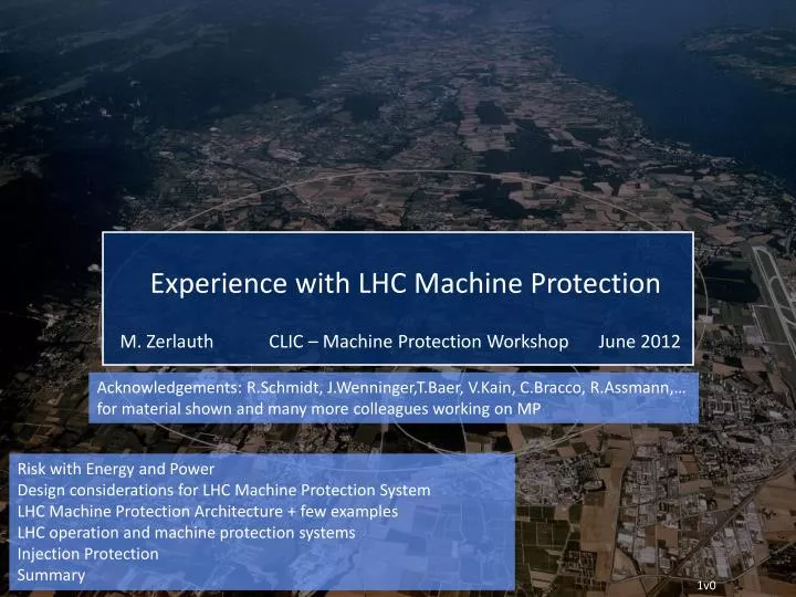
Acknowledgements: R.Schmidt , J.Wenninger,T.Baer , V.Kain , C.Bracco , R.Assmann ,… for material shown and many more colleagues working on MP. Risk with Energy and Power Design considerations for LHC Machine Protection System LHC Machine Protection Architecture + few examples

E N D
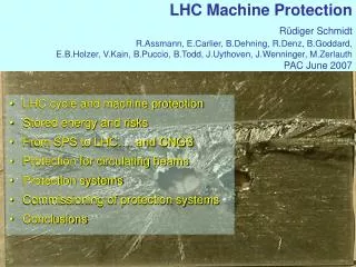
Acknowledgements: R.Schmidt, J.Wenninger,T.Baer, V.Kain, C.Bracco, R.Assmann,… for material shown and many more colleagues working on MP Risk with Energy and Power Design considerations for LHC Machine Protection System LHC Machine Protection Architecture + few examples LHC operation and machine protection systems Injection Protection Summary
Risk with Energy and Power • Design considerations for LHC Machine Protection System • LHC Machine Protection Architecture + few examples • LHC operation and machine protection systems • Injection Protection • Summary
Risk with Energy and Power • Risks come from Energy stored in a system (Joule), and Power when operating a system (Watt) “very powerful accelerator” … the power flow needs to be controlled • An uncontrolled release of the energy or an uncontrolled power flow can lead to unwanted consequences Loss of time for operation or damage of equipment • This is true for all systems, in particular for complex systems such as accelerators • For the RF system, magnet system (LHC=10GJ) … • For the beams (LHC=360MJ/beam) • The LHC is the first accelerator at CERN where machine protection considerations determine daily operation [11] 3
Livingston type plot: Energy stored magnets and beam LHC 10000.00 energy in magnets 1000.00 LHC top energy LHC injection 100.00 (12 SPS batches) Factor ~200 SPS fixed 10.00 Energy stored in the beam [MJ] ISR target, CNGS HERA TEVATRON SPS batch to 1.00 LHC RHIC proton 0.10 LEP2 SNS SPS ppbar 0.01 1 10 100 1000 10000 Momentum [GeV/c] Basedon graph fromR.Assmann [11] 4
What parameters are relevant? • Momentum of the particle • Particle type Activation is mainly an issue for hadron accelerators • Time structure of beam • Energy stored in the beam (synchrotrons and storage rings) one MJoule can heat and melt 1.5 kg of copper one MJoule corresponds to the energy stored in 0.25 kg of TNT • Beam power (linear machines and fast cycling machines) one MW during one second = one MJ • Beam size • Beam power / energy density (MJoule/mm2, MWatt/mm2) increasingly important for future projects, and increasingly complex machines (such as ILC and CLIC, XFEL,..) The energy of an 200 m long fast train at 155 km/hour corresponds to the energy of 360 MJoule stored in one LHC beam Machine protection to be considered for an energy in the beam >> 1 kJ Very important if energy > 1 MJ 5
Protection Functions of LHC MPS BeamEnergy (360 MJ) Beam Dump Beam Protection: 100x energy of TEVATRON 0.000005% of beam lost into a magnet = quench 0.005% beam lost into magnet = damage Failure in protection – complete loss of LHC is possible Powering Protection: MagnetEnergy (9 GJ) Emergency Discharge 10-20x energy per magnet of TEVATRON magnet quenched = hours downtime many magnets quenched= days downtime magnet damaged = $1 million, months downtime many magnets damaged = many millions, many months downtime (few spares) 6
Accidental release of 600 MJoule stored in the LHC dipole magnets (one out of eight sectors, interconnect) during powering tests…without beam! 7
SPS experiment: Beam damage with 450 GeV proton beam Controlled SPS experiment • 81012 protons clear damage • beam size σx/y = 1.1mm/0.6mm above damage limit for copper stainless steel no damage • 21012 protons below damage limit for copper 25 cm 6 cm • Damage limit ~200 kJoule • 0.1 % of the full LHC 7 TeV beams • factor of ~10 below the energy in a bunch train injected into LHC A B D C V.Kain et al 8
Risk with Energy and Power • Design considerations for LHC Machine Protection System • LHC Machine Protection Architecture + few examples • LHC operation and machine protection systems • Injection Protection • Summary
Machine Protection organisational aspects • The risks during LHC operation are known since a long time • Systems for protection were designed and included in the first design report (1995) • beam dumping system • magnet protection system • beam loss monitors • It was realised that an interlock system is required since there is coupling between different systems (~1999) • The work on a coherent interlock system started in 2000 • The beam and powering interlock systems connect to many accelerator systems, and a forum for discussions and decisions was required • Birth of the Machine Protection Working Group in 2001, and in the following a Reliability Sub-Working Group to discuss, define and follow-up the required high dependability systems 10
Design principles for LHC machine protection 1/2 • Protect the machine • highest priority is to avoid damage of the accelerators, requires a very high reliability for detecting failures and stopping operation • Protect the beam • complex protection systems will always reduce the availability of the machine • in the design of protection systems: minimise number of “false” interlocks stopping operation • trade-off between protection and operation (will we every operate with many 10.000 interlock channels?) • Provide the evidence • if the protection systems stops operation (e.g. dumps the beam or inhibits injection), clear diagnostics should be provided • if something goes wrong (near miss or even damage), it should be possible to understand the reason why • diagnostics is frequently not taken seriously enough at design phase, resulting in loss of valuable machine time during later operation 11
Design principles for LHC machine protection 2/2 • Failsafe design • detects internal faults • if protection equipment does not work, stop operation rather than damage equipment • Critical equipment should be redundant (possibly diverse) • Critical processes not by software (no operating system) • no remote changes of most critical parameters • Demonstrate safety / availability / reliability • use established methods to analyse critical systems and to predict failure rate • Managing interlocks (masking during early operation) • LHC: masking only possible if operating with low intensity / low energy beams • Design the system with testing in mind • possibility for remote testing, for example between runs • Appropriate diagnostics implemented in design stage • possibility for efficient data analysis following failures 12
LHC: Strategy for machine protection • Definition of aperture by collimators Beam Cleaning System Powering Interlocks Fast Magnet Current change Monitors Equipment systems,… • Early detection of failures for equipment acting on beams generates dump request, possibly before the beam is affected. • Active monitoring of the beams detects abnormal beam conditions and generates beam dump requests down to a single machine turn. Beam Loss Monitors Other Beam Monitors • Reliable transmission of beam dump requests to beam dumping system. Active signal required for operation, absence of signal is considered as beam dump request and injection inhibit. Beam Interlock System • Reliable operation of beam dumping system for dump requests or internal faults, safely extract the beams onto the external dump blocks. Beam Dumping System • Passive protection by beam absorbers and collimators for specific failure cases. Beam Absorbers 13
Risk with Energy and Power • Design considerations for LHC Machine Protection System • LHC Machine Protection Architecture + few examples • LHC operation and machine protection systems • Injection Protection • Summary
LHC Machine Protection Architecture nQPS / In total, several 10.000 interlock channels than can trigger a beam dump! • MPS architecture is constantly evolving • In addition every year some 100 major changes to operational systems that require tracking and follow-up (threshold changes, maintenance/replacement of components, R2E, operational tools, procedures,…) • Special physics/MD runs require particular attention Courtesy of B.Todd
Machine Protection and Controls • Software Interlock Systems (SIS) provides additional protection for complex but also less critical conditions • The reaction time of those systems will be at the level of a few seconds (much longer than hardware interlock systems) • The systems rely entirely on the computer network, databases, etc – clearly not as safe as HW systems! • Surveillance of magnet currents to avoid certain failures (local bumps) that would reduce the aperture • Sequencer: program to execute defined procedures • Dependable execution of defined and well-tested procedures and operational checks • Logging and PM systems: recording of data – continuous logging and fast recording for transients (beam dump, quench, …) • Very important to understand what happened 16
Magnet Powering Failures with fast effects on beams • Incident in TT40 extraction line revealed danger of nc magnets with low time constants • Powering Failures in normal conducting separation dipoles D1 in IR1 and IR5 found to be fast(est) failure in LHC • 12 modulespowered in series. • βx > 2000m • time constant: , 17
Studies of Fast(est) LHC failure Courtesy of V.Kain 18
Suddenly the AC distribution for CERN fails – no power for LHC! Courtesy of R.Schmidt
Total power cut at LHC - 18 August 2011, 11:45 Monitors detect a change of magnet current in less than one ms and trigger a beam dump before the beam is affected (FMCM, development with DESY)
Orbit for last 1000 turns before power cut 10 micrometer
Risk with Energy and Power • Design considerations for LHC Machine Protection System • LHC Machine Protection Architecture + few examples • LHC operation and machine protection systems • Injection Protection • Summary
Origin of LHC beam dumps and downtime… • Complex LHC Magnet powering accounts for large fraction of premature beam dumps (@3.5TeV, 35% (2010) / 46% (2011) ) • Downtimeafter failures often considerably longer than for other systems • “Top 5 List”: • 1st QPS • 2nd Cryogenics • 3rd Power Converters • 4th RF • 5th Electrical Network • Potential gain: • ~35 days from magnet powering system in 2011 • With 2011 production rate (~ 0.1 fb-1 / day) Courtesy of A.Macpherson 23
Analysis of Protection dumps 1200 beam dumps were cleanly executed during 2011 (-10% wrt to 2010 ) 40% more successful ramps to 3.5TeV ~ Factor of 3 less dumps caused by beam losses, orbit changes,… -> confirm 2010/11 improvements No beam induced quench with circulating beams >100MJ @ 3.5TeV in 2011 No equipment damage observed (apart from kicker erratic causing damage in close by experiment) MPS response of all dumps from 3.5TeV meticulously analyzed and validated – Initiating system always identified, but sometimes not fully clear why it triggered(‘spurious’ triggers, SEUs,…) Beam dumped without beam losses and orbit changes, 107 Beam dumped without beam losses and orbit changes, 208 2010 2011 Nota bene: All statistics only counting fills with E > injection 24
Dependability of MPS backbone Complexity and high level of safety in MPS systems comes at certain cost, i.e. false positives False triggers of most MPS backbone systems remained (surprisingly) constant with time 95% of false dumps in 2011 above injection energy (< thresholds,…) Increase of false positives from QPS (to large extend due to R2E) 22 confirmed SEUs + ‘environment’ related triggers 2010 : 8% of fills dumped due to MPS 2011 : 12.6% of fills dumped due to MPS 7.7% not accounting for SEUs
Dependence of faults on intensity Beam Intensity [1E10 p] / # fault density • Strong dependence of fault density on beam intensity / integrated luminosity • Peak of fault density immediately after each technical stop?! • Much improved availability during early months of 2011 and ion run -> Confirm potential gain of mitigations related to radiation effects on protection electronics
Risk with Energy and Power • Design considerations for LHC Machine Protection System • LHC Machine Protection Architecture + few examples • LHC operation and machine protection systems • Injection Protection • Summary
SPS, transfer lines and LHC Beam is accelerated in SPS to 450 GeV (stored energy of 3 MJ) Beam is transferred from SPS to LHC Beam is accelerated in LHC to 3.5 TeV (stored energy of 100 MJ) IR8 Injection kicker CNGS Target Switching magnet Scraping of beam in SPS before transfer to LHC Single pass – fully relying on passive protection! Fast extraction kicker SPS 6911 m 450 GeV / 400 GeV 3 MJ Acceleration cycle of ~10 s Transfer line 3km Injection kicker LHC IR2 Fast extraction kicker 1 km Transfer line
Injection Scheme TDI Miss-kicked Injected batch MKI grazing Circulating LHC beam grazing Injected batch - Kicked Circ. beam - Over-kicked inj. batch Most critical Injected beam: Nominal kick No kick ¾ kick Grazing
TDI grazing • Nominal MKI kick = 0.85 mrad • TDI grazing: • Injected beam: 86% kicker strength Beam 1 IP2 TDI MKI MQM D1 D2 MQX MQX Injected beam TCDD Courtesy of C.Bracco
Loss Pattern following kicker erratic Upstream of IP2 TDI Beam 1 Losses starting at TDI, no injection loss signature only circulating beam kicked by MKI Downstream of IP2 Insertion losses: 3 magnets quenched (D1.L2, MQX.L2, D2.R2) Beam 1
Risk with Energy and Power • Design considerations for LHC Machine Protection System • LHC Machine Protection Architecture + few examples • LHC operation and machine protection systems • Injection Protection • Summary
Summary 1/2 Machine protection should always start during the design phase of an accelerator • Particle tracking • to establish loss distribution with realistic failure modes • Calculations of the particle shower (FLUKA, GEANT, …) • energy deposition in materials, activation of materials, accurate 3-d description of accelerator components (and possibly tunnel) required • Coupling between particle tracking and shower calculations Machine protection • is not equal to equipment protection • requires the understanding of many different type of failures that could lead to beam loss • requires comprehensive understanding of all aspects of the accelerator(physics, operation, equipment, instrumentation, functional safety) • touches many aspects of accelerator construction and operation • includes many systems • is becoming increasingly important for future projects, with increased beam power / energy density (W/mm2 or J/mm2 ) and complex machines
Summary 2/2 LHC Machine Protection Systems have been working very well during first years of operation, thanks to continuous rigor of operation crews and MPS experts Ever more failures are captured before effects on beam are seen (no losses or orbit movements) Still no quenches with circulating beam (with ~ 100MJ per beam and 10mJ for quenching a magnet) Additional active protection will provide further essential redundancy for next years of running (beam current change monitors, additional SW interlocks…) Injection protection remains a critical item for machine protection One has to remain extremely vigilant to maintain level of safety of protection systems while increasing efforts on increasing MPS availability
Summary Machine protection • is not equipment protection • includes many systems • requires the understanding of many different type of failures that could lead to beam loss and possible damage • requires fairly comprehensive understanding of the accelerator (accelerator physics, operation, equipment, instrumentation, …) • touches many aspects of accelerator construction and operation • needs close collaboration between many teams • is along with the quality of the provided monitoring and diagnostics data a driving factor for efficient operation of complex machines as the LHC
Risks and protection (examples for beam loss) • Protection is required since there is some risk • Risk = probability of an accident (in accident per year) • consequences (in Euro, downtime, radiation dose to people) • Probability of an accident (e.g. uncontrolled beam loss) • What are the failure modes that lead to beam loss into equipment (there is an practical infinite number of mechanisms to lose the beam) • What is the probability for the most likely failure modes? • Consequences of an uncontrolled beam loss • Damage to equipment • Downtime of the accelerator for repair (spare parts available?) • Activation of material, might lead to downtime since access to equipment is delayed • The higher the risk, the more protection is required
LHC Machine Protection System (initial design) Interlock conditions 24 ~ 20000 ~ 1800 ~ 3500 ~ few 100 ~ few 100 • MPS ‘backbone’ consists of magnet and beam interlock system, LBDS, active detection systems (BLM, BCM, QPS, SIS,…), injection protection, collimation,… • Additional inputs from many equipment systems to preventively dump beams • In total many 10.000 interlock conditions MPS backbone
Systems detecting failures and Beam Interlocks (initial design) Beam Loss Monitors BCM Jaw Position Temperature Operator Buttons CCC LHC Experiments RF System Collimation System Beam Dumping System Beam Interlock System Injection Interlock Vacuum System Powering Interlocks superconducting magnets Powering Interlocks normal conducting magnets Access System Beam loss monitors BLM Timing System (Post Mortem Trigger) Magnets Power Converters Monitors aperture limits (some 100) Monitors in arcs (several 1000) Magnet protection system PS (20000 channels) Power Converters ~1600 Cryogenics some 10000 channels
Safe deposition of stored energy / power Energy in the LHC beams • Beam cleaning with collimators, limiting particle losses around the accelerator • Beam loss monitors to detect beam losses, and requesting a beam dump when beam losses too high • Regular and irregular beam extraction discharging beam energy into a specially designed target (beam dump block) • Stop injection Energy in the magnets • After a quench: discharge the magnet energy into the magnet coils (quench heaters) • Discharge the energy stored in the electrical circuit into resistors (energy extraction) • Stop power converters • …….and dump the beam as fast as possible 40
Systems detecting failures and Beam Interlocks(today) Safe Beam Parameter Distribution Beam Loss Monitors BCM Jaw Position Temperature SpecialBLMs Safe LHC Parameter Software Interlock System (complex decisions) Operator Buttons CCC LHC Experiments Screens and Mirrors beam observation RF System Collimation System Beam Dumping System Beam Interlock System Safe Beam Flag Injection Interlock Vacuum System Powering Interlocks superconducting magnets Powering Interlocks normal conducting magnets Fast Magnet Current Monitor Access System Beam loss monitors BLM Timing System (Post Mortem Trigger) Magnets Power Converters Monitors aperture limits (some 100) Monitors in arcs (several 1000) Magnet protection system PS (20000 channels) Power Converters ~1600 AUG UPS Cryogenics some 10000 channels
Beam losses, machine protection and collimation Continuous beam losses: Collimation prevents too high beam losses along the accelerator (beam cleaning) A collimation system is a (very complex) system installed in an accelerator to capture mostly halo particles Such system is also called (beam) Cleaning System Accidental beam losses: “Machine Protection” protects equipment from damage, activation and downtime Machine protection includes a large variety of systems 42
Regular and irregular operation Regular operation Many accelerator systems • Continuous beam losses • Collimators for beam cleaning • Collimators for halo scraping Failures during operation • Beam losses due to failures, timescale from nanoseconds to seconds Machine protection systems Collimators Beam absorbers 43
Beam losses in accelerators Particles are lost due to a variety of reasons: beam gas interaction, losses from collisions, losses of the beam halo,….… • Continuous beam losses are inherent to the operation of accelerators • To be taken into account during the design of the accelerator • Accidental beam losses are due to a multitude of failures mechanisms • The number of possible failures leading to accidental beam losses is (nearly) infinite 44
Beam losses and consequences Particle losses lead to particle cascades in materials that deposit energy in the material the maximum energy deposition can be deep in the material at the maximum of the hadron / electromagnetic shower The energy deposition leads to a temperature increase material can vaporise, melt, deform or lose its mechanical properties risk to damage sensitive equipment for some 10 kJ, risk for damage of any structure for some MJoule (depends on beam size) superconducting magnets or cavities could quench (beam loss of ~mJ to J) Equipment becomes activated due to beam losses (acceptable is ~1 W/m, but must be “As Low As Reasonably Achievable” - ALARA)
Energy deposition and temperature increase There is no straightforward expression for the energy deposition The energy deposition is a function of the particle type, its momentum, and the parameters of the material (atomic number, density, specific heat) Programs such as FLUKA, MARS, GEANT and others are being used for the calculation of energy deposition and activation Other programs are used to calculate the response of the material (deformation, melting, …) to beam impact (mechanical codes such as ANSYS, hydrodynamic codes such as BIG2, AUTODYN and others) Question: what is dangerous (stored beam energy, beam power)? When do we need to worry about protection?
DIDT Beam Current Change Monitor was vital part of MPS systems for e.g. HERA Proposed for use in LHC MPS in 2005 (EDMS Doc. 359172) With HERA like system, changes of < 0.1% of total beam current could be captured in 10 turns BI started development (with DESY consultancy) mid 2010, for deployment end 2011 + 2012 run First system installed and data recorded, but showing not understood effects of bunch length,…? Important to validate and finish soon, as such system adds layer of protection when probing quench/UFO limits with > BLM thresholds DIDT BCT First system now installed in IR4 First measurements during proton runs Courtesy of M.Pfauwadel, D.Belohrad
Work ongoing: Novel PC Interlock System In addition to existing SIS interlocks at injection, ramp, squeeze and SB, new SW interlock system monitoring PC currents to protect against operations- and feedback- failures Redundant to SIS for arcs, adds protection for LSS 1/2/5/8 due to capability of tracking bump shape amplitude/variations Key interest for all other (non-COD) converters where currently no current tracking is done Currently under commissioning and testing, after initial experience connection to BIS B1, V Distribution of RT max kick difference to BP reference during ramp 1 bad BPM Fill 1717: Bump >2mm during ramp in IR7 Courtesy of K.Fuchsberger
Other improvements for 2012 - ADT Considerable work went into finalization and commissioning of transverse damper MDs demonstrated selective and very deterministic bunch blow-up Allows for abort gap cleaning and increased efficiency when performing loss-maps, quench MDs,… System fully operational for both beams, should become default procedure as of start-up 2012 onwards ADT blow up 3rd order resonance Blow up of selected bunches during MD (left) and unaffected bunches (right) Loss-maps performed with ADT and 3rd order resonance method Courtesy of W.Hofle
Classification of failures affecting the beam • Type of the failure • hardware failure (power converter trip, magnet quench, AC distribution failure such as thunderstorm, object in vacuum chamber, vacuum leak, RF trip, kicker magnet erratic firing, .…) • controls failure (wrong data, wrong magnet current function, trigger problem, timing system, feedback failure, ..) • operational failure (chromaticity / tune / orbit wrong values, …) • beam instability (due to too high beam / bunch current) • Machine state when failure occurs: operational scenarios • Injection (single pass) • Stored beam at injection energy, during acceleration and at top energy • Extraction (single pass) • Parameters for the failure • time constant for beam loss • damage potential • probability for the failure 50