Download
1 / 71
710 likes | 838 Views
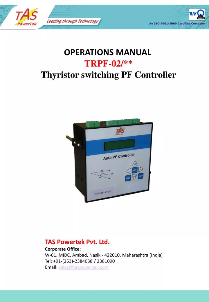
OPERATIONS MANUAL TRPF-02/** Thyristor switching PF Controller. TAS Powertek Pvt. Ltd. Corporate Office: W-61, MIDC, Ambad, Nasik - 422010, Maharashtra (India) Tel: +91-(253)-2384038 / 2381090 Email: sales@taspowertek.com. NOTE

E N D
OPERATIONS MANUAL TRPF-02/** Thyristor switching PF Controller TAS Powertek Pvt. Ltd.Corporate Office: W-61, MIDC, Ambad, Nasik - 422010, Maharashtra (India)Tel: +91-(253)-2384038 / 2381090Email: sales@taspowertek.com
NOTE These instructions do not purport to cover all details or variations in equipment, nor to provide for every possible contingency to be met in connection with installation, operation or maintenance. Should further information be desired or should particular problems arise which are not covered sufficiently for the purchasers purposes, the matter should be referred to our TAS PowerTek Pvt. Ltd. office. The contents of this instruction Manual shall not become part of or modify any prior or existing agreement or relationship. The sales contract contains the entire obligations of TAS PowerTek. The warranty contained in the contract between the parties is the sole warranty of TAS PowerTek. Any statements contained herein do not create new warranties or modify the existing warranty. The reproduction, transmission or use of this document or its contents is not permitted without express written authority. Offenders will be liable for damages. All rights are reserved.
Index Index Page ------------------ 1 Ordering Information ------------------ 2 Features ------------------ 3 Specifications ------------------ 4 Mechanical Dimensions/ mounting --------- 5 Terminal Arrangement ------------------ 6 Connector Details ------------------ 7 Front Plate indications & keyboard --------- 9 Various Installation Schemes ---------------- 12 Control Wiring ------------------------------- 15 CT Selection ---------------------------- 18 PF compensation Methodology -------------- 19 Front LCD Display ---------------------------- 21 Method for Keyboard/Display usage --------- 27 Auto and Manual Operation Mode ----------- 30 Parameter Editing EDIT: Display ----------------- 32 EDIT: General ----------------- 33 EDIT: System ----------------- 35 EDIT: Communication -------- 39 EDIT: Fault -------------------- 41 EDIT: Step -------------------- 43 Recommendations: Thyristor APFC panel ---- 48 APFC panel Commissioning Instructions Before Power Up -------------- 50 After Power Up --------------- 53 Fault Finding Guidelines ---------------------- 55 Annexure-1: Default Parameter list ---------- 57 Annexure-2: TAS-01 Communication Protocols. 63 After Sales Service contact and Sales Outlets ------------------------------ 68 - 1 -
Ordering Information. • TRPF-02 /NN/V /S • NN- Indicates the number of output channels. Here numbers can be • 04, 06, 08, 12, 16. • V- Indicates rated voltage . • 3: here will indicate 415Vac Line-Line. • 2: here will indicate 240Vac. Line-N. • 1: here will indicate 110Vac. Line-Line. • 0: here will indicate 63.5Vac. Line-N. • S- Indicates the special functions. • N: Indicates no special function. • R: Indicates RS-232 port availability. • D: Indicates Data Logging capability. • RD: Indicates RS-232 + Data logging. • The type no of the units to be ordered should be mentioned on the Purchase Order. - 2 -
Features: • Suitable for Thyristorised high speed capacitor switched panel. • THD measurements with supply voltage, current and the capacitor current. • Various possibilities for bank selection. Including user defined bank values in kVAr. • Input sensing either through line to line voltage with a CT or Individual phase with a CT. Programmable PT ratio for HT feedback. • Selectable current input range. • 1Amp and 5Amp.(CT input) • Protection against • Over/Under Voltage. • Over/Under cap. Amp / THD. • Over/Under frequency. • + many more. • Compensation on fundamental waveform kVAr calculation, with effects of supply frequency and voltage. • Digital open emitter output commands of +12Vdc and Digital fault input sensing. • Capable of giving correction every cycle of mains waveform. • Standard 144 X 144 mm panel flush mounting arrangement. Max depth 75mm. Back side. - 3 -
Specifications: • Operating Voltage: • for 415V line to line config:300V to 500V • for 240V Phase to N config:170V to 300V • for 110V line to line config: 79V to 132V • for 63.5 Phase to N config: 45V to 76V • Current Input: 1A.or 5A. • (Load Current full range.) • Capacitor current Input: 1A or 5A. • 12Vdc/20mA solid state Outputs (open • Emitter) for Thyristor switch commands. • Short circuit protected outputs. • 12Vdc digital input channels for sensing • the digital inputs (thyristor step fault f.b.) • from thyristor switch. • Measurement accuracy: • Class-1 • Operating temperature • 0 to 50°C. • Storage temperature • -10 to +75°C • Output commands models • for 4, 6, 8, 12 and 16 output. - 4 -
All Dimensions in mm. 135 144 135 144 70 6 Mechanical Dimensions Recommended cutout for panel front door is 138mm X 138mm. - 5 -
Top Side Connector Arrangement: Aux Output NO contacts. Fault Feedback Input Terminals. 12Vdc Aux.Input. Bottom Side Connector Arrangement: Mains Feedback CT input. Auxiliary Supply / Voltage feedback Cap.Current Feedback CT input. ON/OFF Command Output Terminals. Terminal Arrangement. - 6 -
CONNECTOR DETAILS: • Top Side Connectors: • Fault Feedback Terminals: • Terminals marked with TFB1 ---- TFBnn and COM. • COM: The reference voltage level with respect to this terminal the other digital voltages of +12Vdc are given to TFBnn. • TFBnn: The number nn is normally connected to corresponding step number nn thyristor switching fault feedback. These are +12Vdc signals given by thyristor switches whenever these trip due to any fault that is observed in the specific step. • Auxiliary Input: • Terminals marked with AI & COM. The various functions like: • Output Disable / Enable. • Mains / Generator Mode change-over. • Faults reset. • The function out of these is selected through user settable parameter. The Logic’1’ is with +8V to +14Vdc at the input terminal ‘AI’ with respect to ‘COM’ and Logic’0’ is with 0 to +0.5Vdc. • Auxiliary Output: • Terminals marked with AO & AO. These are Normally Open auxiliary contacts. Maximum contact rating is 0.5Amp/240Vac or 100mA/48Vdc. This is used for getting the outputs control of: • Output tripped fault. • Indicative + tripped fault. (system fault) • Out of Step. (Inadequate compensation) • Reset modem (In case of communication failure with GSM modem) • The function out of these is selected through user settable parameter. • For inductive switching loads like contactor/ relay coils, it is recommended to use the RC snubber circuits for AC and free wheeling diode for DC. The values can be as per coil inductance section. Typically it is R=330/2Watt, C=0.1F/1000V for 240Vac system. - 7 -
CONNECTOR DETAILS: Bottom Side Connectors: Mains CT Feedback Terminals: Terminals marked with LC + & -. These are connected to secondary of the Mains current feedback CT secondary. The rated secondary can be either 5Amp. or 1Amp. ac. (Selectable by user defined parameter). Capacitor CT Feedback Terminals: Terminals marked with CC. These are connected to secondary of overall capacitor current sensing CT. Rated secondary current can be either 5Amp or 1Amp ac. (User defined parameter). On/Off Command Output Terminals: Terminals marked with OP1 ----- OPnn and GND. GND: This is the Ground reference terminal. With respect to this terminal, the output commands OPnn reference voltages are given. OPnn: These are the Bank On / Off command terminals. When a specific capacitor bank is to be turned On, it generates output Voltage as +11V to +12Vdc. This is through the solid state switch which has maximum driving capacity of 20mA. Each output is protected for short circuit. Auxiliary Supply / Voltage Feedback Terminals: Terminals are marked with L1 / P and L2 / N. These are used for giving the mains voltage input to the relay. This voltage would be used for Powering up the relay as well as for taking the voltage feedback. 415Vac and 110Vac are considered as line voltages. (across lines of the two phases). 240Vac and 63.5Vac are considered as phase voltages. (across line and Neutral. - 8 -
16Charactor X 2 lines LCD display. RS-232 Serial Communication Port. Soft touch Keypad. Front Plate Indications and Keyboard. - 9 -
Scroll/Cursor moment keys Data Entry Key Mode selection Save Parameter Data Soft touch Keypad: Right Shift cursor Increment Data / Page. Left Shift cursor Decrement Data / Page. Enter Data / Mode. Select Mode of Operation. Save the Data - 10 -
5 4 3 2 1 6 7 8 9 RS-232 serial communication 9 pin D connector: RXD GND TXD RS-232 cable connection Details: - 11 -
Load CT. L O A D Cap. CT. HT side LT side Conventional LT side PF improvement system Schematic: Various Installation Schemes. Scheme-1. As per this scheme, the load sensing CT is put between the Source and the PF correction Capacitor banks. This is as per the diagram shown above. The voltage feedback is taken from the LT bus system itself. This type of scheme is used when user is interested in maintaining the healthy Power Factor on the secondary side of the transformer. This scheme is preferred with LT consumers of electricity, where the metering is carried out on LT side. Capacitor current feedback is taken from all the capacitor banks that are controlled by the Auto PF controller: TRPF-02. i.e. the capacitor current feedback CT senses the overall current of the capacitor banks in the circuit. - 12 -
CT / PT L O A D HT side LT side Cap. CT. LT Power Factor compensation with HT side feedback: Scheme-2. As per this scheme, the load sensing CT as well as voltage feedback PT is put at the input of the transformer on HT side. This scheme is preferred with LT consumers of electricity, where the metering is carried out on HT side. Using this scheme gives even the compensation against magnetising current of the transformer. Thus, for HT metering, able to give more accurate results. Capacitor current feedback is taken from all the capacitor banks that are controlled by the Auto PF controller: TRPF-02. i.e. the capacitor current feedback CT senses the overall current of the capacitor banks in the circuit. This feedback is common in all the schemes. The relay has provision to program the HT PT ratio as well as defining the capacitor working voltage. - 13 -
HT side LT side L O A D Mains CT. Cap. CT. Generator. Usage of summation CT for usage with Mains / Generator changeover system. Scheme-3. In case of system with duel sources of supply, I.e. Supply Grid and Generator. Under such case, the system can be shifted between the two sources. For every source there may be different requirements of max. loading on sources as well as requirements for different target PF settings. With such schemes, a summation CT is used. The changeover between the two sources is informed to TRPF-02 through its Aux. Input port. TRPF-02 is capable of handling such duel settings. Using this scheme gives user an advantage of using a single PF improvement system with either of the source in operation. Capacitor current feedback is taken from all the capacitor banks that are controlled by the Auto PF controller: TRPF-02. - 14 -
MAINS SOURCE L1 L O A D L2 L3 N P1 P2 S1 S2 Thyristorised Switching. TRPF-02 + - L2 L1 CC LC N P OP1—OPnn TFB1--TFBnn P1 P2 S1 S2 V, I and I-cap feedback Control Wiring: • The control wiring for Measurement section: • This is further divided into two types. • Quadrature Mode. For 415Vac and 110Vac. • In phase Mode. For 240Vac and 63.5Vac. • Quadrature Mode: Typical Schematic. - 15 -
P1 P2 S1 S2 MAINS SOURCE L1 L O A D L2 L3 N P1 P2 S1 S2 Thyristorised Switching. TRPF-02 + - P N CC LC L1 L2 OP1—OPnn TFB1--TFBnn In Phase Mode: Typical Schematic. Either of the above specified modes can be selected by the user based on the system requirement. Whats is looked into is that with Quadrature Mode is Voltage across L1 & L2 terminals is the line voltage value as compared to In Phase mode has Phase ‘P’ to Neutral ‘N’ voltage value. Therefore the relay voltage selection should be done according to the mode of operation selected. - 16 -
INPUT Rph ctrl Rph Ctrl Yph Ctrl Yph ctrl Bph Ctrl Bph ctrl Neutral Neutral N B Y R R R R R R R Y Y Y Y Y Y B B B B B B 415 Vac. L 1 L 2 L C + L C - C C + A I + A O A I - C C - A O C O M T FB 1 T FB 2 T FB 3 T FB 4 T FB 5 T FB 6 FLT RST AO AO FLT F/B CMD 12P GND RESET O P 6 Thyristor Switch ZCTC- /02 O P 5 OUTPUT O P 4 O P 3 O P 2 O P 1 G N D TRPF-02/06/T*/3. 12V DC FLT F/B1 FLT F/B3 FLT RST CMD 2. 12P GND FLT F/B2 CMD 1. CMD 3. 12V DC OUTPUT 3 RESET Thyristor Combi-Pack ZCCP- /03 OUTPUT 2 INPUT OUTPUT 1 Typical Scheme of TRPF-02 with TAS make Thyristor switches. - 17 -
CT Selection: For Mains Current Feedback: Normally the Primary current rating of the CT is equal to the maximum capacity of the mains source current. But sometimes, even with source having more capacity, the Load requirements are comparatively small. Under such case its recommended to use the CT rating equal to the maximum known Load current. This will give better results and also gives better accuracy of measurement. The secondary of the CT can either be 5Amp ac or 1Amp ac. The VA rating of the CT should be minimum 3VA, even though the actual VA burden offered by TRPF-02 is less than 0.5VA. This is to take care of longer lead lengths and contact drops. For Capacitor Current Feedback: Here the primary current rating of the CT should be equal to the maximum current that can flow through the PF correction system. The secondary of the CT can either be 5Amp ac or 1Amp ac. The VA rating of the CT should be minimum 1VA, even though the actual VA burden offered by TRPF-02 is less than 0.5VA. General about CT connection: The CT secondary should be brought to TRPF-02 terminals through a terminal block. This block should have arrangement to short the CTs. This is to take care of CTs being left open circuited and thus getting damaged, when TRPF-02 terminals are removed. - 18 -
PFUPPER & PFLOWER both set as inductive: PFLOWER. PFLOWER. KVAR (Ind) smallest Capacitor bank KVARX1.5 width. PFUPPER. PFUPPER. - KW. KW. KVAR (Cap) No change band. Capacitor Addition band. Capacitor Removal band. PFUPPER as Capacitive & PFLOWER as inductive: KVAR (Ind) smallest Capacitor bank KVARX1.5 width. PFLOWER. PFLOWER. - KW. KW. PFUPPER. PFUPPER. KVAR (Cap) PF Compensation methodology in TRPF-02: - 19 -
PFUPPER & PFLOWER as Capacitive: KVAR (Ind) smallest Capacitor bank KVAR X 1.5 width. - KW. KW. PFLOWER. PFLOWER. PFUPPER. PFUPPER. KVAR (Cap) No change band. Capacitor Addition band. Capacitor Removal band. All the three conditions specified in the diagram, the four quadrant operation is achieved if “Auto kW polarity” is not activated. If this feature is activated, the TRPF-02 works with only kW +ve two quadrants. Thus, with 4 quadrant operations requirements, Auto kW polarity should be kept off. Typical example of 4 quadrant operation is with “Co-Generation Plants” and “Wind-Power Generation”. But with most conventional consumer applications, only +ve KW is seen, where the Auto kW polarity feature can be kept ON. It can be seen that there are two PF set points to be set in TRPF-02. The Upper and the Lower. TRPF-02 ensures that PFUPPER is never exceeded. Additionally, “No change band” to minimum KVAR band size equal to smallest bank KVAR X 1.5 ensures no hunting during the low KW loading. - 20 -
The contrast of the LCD can be adjusted by using the keys. The left key will make the contrast darker and right key will make it lighter. The front LCD Display under default condition displays the various parameter readings. There are number of screens that shows the various parameters that are measured or derived. These various screens can be displayed by pressing the Scroll keys. Viz. UP key - DOWN key – Alternately, scrolling of all the screen with user defined interval can also be set by Parameter settings. TAS Power Tek TRPF-02-Ver* 1 2 3 4 5 6 7 8 9 10 11 12 13 14 15 16 Front LCD Display Power Up Display Screen. (Only for first 1 sec.) - 21 -
This is the factory set default screen. The “COS=” part is to indicate that the value following that is “Power Factor”. This indicates the PF that is sensed by the unit near the load sensing CT position. i.e. the transformer/ supply grid side. Further three digits are to indicate if PF sensed is Inductive or Capacitive. Inductive is shown by “IND” and Capacitive is shown by “CAP”. TRPF-02 is designed to work with two set points. One group of set points are for Transformer /Supply Grid and other group of set points are for Generator operation. Transformer / Supply Grid operation is indicated by “” and Generator operation is indicated by “”. The last digit on the upper line of display shows the operation mode. TRPF-02 is designed to work in two modes. Viz. Auto mode and Manual mode. Auto mode is indicated by “A” and Manual mode is indicated by “M”. The bottom line of the LCD display shows the capacitor bank status. The numbers 1 to 16 below the LCD display are for specific outputs. (capacitor bank number that is controlled by TRPF-02). The LCD display above this number gives the status of that specific output/Capacitor bank. Total blank “ ” indicates that that output is not used for control. A small dash indicates that Bank is connected but is in OFF state. A symbol indicates that bank is connected and it is in ON state. A symbol indicates that bank is declared as fixed bank and is ON. A symbol indicates that bank is declared faulty and is OFF. COSφ=1.ØØØ INDA 1 2 3 4 5 6 7 8 9 10 11 12 13 14 15 16 Then the unit should display: Display Page: 00 - 22 -
COSφ=0.986 INDA Mains Voltage ØØØ417.7 V 1 2 3 4 5 6 7 8 9 10 11 12 13 14 15 16 1 2 3 4 5 6 7 8 9 10 11 12 13 14 15 16 For an example, If the screen seen is as below means: Power Factor at Load sensing CT is 0.986 Inductive. System is compensating Transformer/Supply grid. Unit is operating in Auto mode. Total number of banks that are operational are seven. Bank no.1 is declared as fixed and is in ON condition. Bank no.2, 3 and 7 are in ON condition. Bank no.4 & 6 are in OFF condition. Bank no.5 is declared as faulty. The detailed meaning of System operation, mode, fixed bank, bank operational, discharging etc would be explained in more detail in the later part of manual. (Edit Parameter “Step”) Displaying of other Parameters: The other system related parameters can be observed by Scroll up/down keys. Next screen on pressing Scroll down displays the Mains Voltage. This is the voltage that is displayed at the input terminals of the TRPF-02. In case intermediate PT is used then this will indicate the voltage at primary of that PT. Display Page: 01 - 23 -
Mains Current 0731.9 A C-KVAR 00220.8 Reactive Power 00066.6 KVAr Active Power 00525.3 KW Apparent Power 00529.5 KVA Cap-Current 0305.2 A 1 2 3 4 5 6 7 8 9 10 11 12 13 14 15 16 1 2 3 4 5 6 7 8 9 10 11 12 13 14 15 16 1 2 3 4 5 6 7 8 9 10 11 12 13 14 15 16 1 2 3 4 5 6 7 8 9 10 11 12 13 14 15 16 1 2 3 4 5 6 7 8 9 10 11 12 13 14 15 16 1 2 3 4 5 6 7 8 9 10 11 12 13 14 15 16 Further press the Scroll down key displays Load current at the Sensing CT. Overall Capacitor current sensed by Capacitor current CT. Active Power i.t.o. KW that is sensed by the relay. This is at the source/transformer side. Reactive Power i.t.o. kVAr that is sensed by the relay. This is again source/ transformer side. –ve sign indicates capacitive PF. Apparent Power i.t.o. KVA that is sensed by the relay. This is source/transformer side value. KVAR value offered by the Compensating capacitor. This is reactive KVAR given by Auto PF correction system. Display Page: 02 Display Page: 03 Display Page: 04 Display Page: 05 Display Page: 06 Display Page: 07 - 24 -
Load Side KVAR 00287.4 Load Side KVA 00598.8 Current THD-# 012.9 % Load Side COSφ 0.877 IND Voltage THD-# 002.1 % Frequency 50.2 Hz 1 2 3 4 5 6 7 8 9 10 11 12 13 14 15 16 1 2 3 4 5 6 7 8 9 10 11 12 13 14 15 16 1 2 3 4 5 6 7 8 9 10 11 12 13 14 15 16 1 2 3 4 5 6 7 8 9 10 11 12 13 14 15 16 1 2 3 4 5 6 7 8 9 10 11 12 13 14 15 16 1 2 3 4 5 6 7 8 9 10 11 12 13 14 15 16 Load side kVAR value. This is the value without any capacitive compensation. Load side kVA value. Load side Power Factor value. Operational Grid frequency. Voltage Total Harmonic Distortion in %. # is either F or R user defined parameter. THD-F: THD fundamental. THD-R: THD RMS value. Source/ Transformer current THD in %. Display Page: 08 Display Page: 09 Display Page: 10 Display Page: 11 Display Page: 12 Display Page: 13 - 25 -
Cap Cur THD-# 018.5 % Temperature 36 Deg C TAS Software Ver TRPF02-1.2 Time: 17:01:12 Date: 26/09/04 1 2 3 4 5 6 7 8 9 10 11 12 13 14 15 16 1 2 3 4 5 6 7 8 9 10 11 12 13 14 15 16 1 2 3 4 5 6 7 8 9 10 11 12 13 14 15 16 1 2 3 4 5 6 7 8 9 10 11 12 13 14 15 16 Capacitor current THD in % Temperature inside the housing of TRPF-02. This screen only with “R” and “RD” versions. Displays the RTC (Real time clock) time and date. Time in hh:mm:ss format. Date in dd:mm:yy format. The firmware version used. As product is constantly under up-gradation, this may change depending on date of supply. Display Page: 14 Display Page: 15 Display Page: 16 Display Page: 17 Further pressing of scroll down key will bring the display back to Page no.00. Similarly, by pressing scroll up key, the display pages in reverse sequence can be seen. The display can even be put in “Auto Scroll” with changeover time as defined in user defined parameters. - 26 -
PRESS If Password Option is Enable/Disable. Enable Disable Default Display mode Enter Password: Enter the 4 Digit password By use of & Keys. PRESS IF PASSWORD Correct? COSφ=1.ØØØ INDA NO YES * 1 2 3 4 5 6 7 8 9 10 11 12 13 14 15 16 Method for Keyboard/Display usage. Flow chart for entering into different modes: - 27 -
* Default Display mode COSφ=1.ØØØ INDA 1 2 3 4 5 6 7 8 9 10 11 12 13 14 15 16 Select 1.Edit Parameter Select 2.Auto Operation Select 3.Manual Opern # - 28 -
Default Display mode COSφ=Ø.876 INDM COSφ=Ø.92Ø INDA COSφ=1.ØØØ INDA 1 2 3 4 5 6 7 8 9 10 11 12 13 14 15 16 # Select 1.Edit Parameter Select 2.Auto Operation Select 3.Manual Opern Operation in Auto Operation in Manual Mode. Mode. Edit Parameters Display Display related parameters. General parameters Grid / Transformer / APFC system related parameters Only with “R” & “RD” versions. Communication related parameters. Fault trip settings. Capacitor bank step settings. Edit Parameters General Edit Parameters System Edit Parameters Communication Edit Parameters Fault Edit Parameters Step - 29 -
Auto and Manual Operation Modes: Before Understanding the Parameter Editing, lets understand the two modes of operation. “Auto” and “Manual” Auto Operation: Select 2.Auto Operation On this screen pressing “ENT” key will put the unit in Auto Operation. This mode will continue till alternate operation mode is selected or unit is put in Power down condition. This is the mode in which the unmanned operation of automatically putting the capacitors in and out of circuit is performed. This mode should be normally selected with TRPF-02, once the system is totally commissioned. Here the kVAr compensation values are calculated by TRPF-02 and the closest equivalent capacitor combination is inserted in the system so that the PF is maintained within the desired level. This is as per the kW v/s kVAr graphs shown earlier in PF compensation part. On the default display, the status of capacitor banks is seen as performed by TRPF-02. Any TFB (Thyristor switch fault Feed Back) commands from thyristor switches will be considered as that specific capacitor bank is faulty and TRPF-02 will not use this bank for compensation. It will try to use the other capacitor banks to select the best possible combination of the banks to achieve target kVAr. (i.e. target PF). TRPF-02 assumes that the thyristor switches used are Zero spike current switch On thyristor switches (Like TAS ZCTC or ZCCP). Thus the control command to multiple banks switch ON/OFF can be simultaneous in Auto mode. - 30 -
Manual Operation: Select 3.Manual Opern • Pressing “ENT” button on this screen will put TRPF-02 in Manual mode. This mode would continue to run till it is purposefully changed or Power down. • This mode is normally used to perform the Operation like: • Resetting of faulty banks to healthy status. • Checking the Capacitor banks by turning them ON/OFF. • Declaring specific bank/s faulty. Masking of the banks so that once auto mode is selected, these faulty declared banks would not be used. • For Declaring banks faulty or Resetting faulty banks: • In manual mode default screen press “ENT”. • The cursor above bank 1 will start blinking. Use keys to select the specific bank. Then use key to declare the bank faulty. • To reset the faulty bank, bring the blinking cursor to that bank and use key to declare the bank as healthy. • Once the specific banks are declared faulty or reset from faulty to a healthy status, press “ENT” key so that cursor stops blinking. • For saving the status on permanent basis (so that even after Power down, the status is unchanged), press “SAVE” key. After this save command, the unit will jump back to default mode. (Default as auto or manual is set in edit parameters). • For Testing banks with manual On/ Off commands: • Press “ENT”, the cursor will start blinking. Use keys to select the specific bank/s that are healthy and use key to turn On and use key to turn Off the capacitor banks. To come out of Manual On/Off edit mode, press “ENT” key so that cursor stops blinking. - 31 -
Save the entered Information and go to the default display page Parameter Editing: Edit Parameters Display Fonts shown in Blue color are editable. In LCD Display, they are still black in color. For adjustment of contrast of the LCD display. The number lowering would make the LCD darker. Note the method of editing the parameter. press “Enter”, then edit with scroll keys, change to correct value and press “Enter”. This indicates the page number that should be displayed as default. This parameter is not of significance if Auto-Scroll is enabled. This option allows the user to decide the display to scroll automatically or only with pressing of scroll up/down keys. Auto scroll enable will scroll display at the fixed user defined interval. After going to last 16th or 17th page, it will jump back to 0th page. This parameter decides the scrolling interval in seconds. This parameter is not used if Auto Scroll is disabled. TRPF-02 displays the %THD of various parameters. If this display required is with respect to RMS value, select R-THD. If this display required is with respect to fundamental value, select F-THD. (Its for user to make choice as per the convenience) LCD Contrast :05 Edit Parameter Default Display Page No :00 Auto Scroll Disable :0 Auto Scroll Enable :1 Scroll Time Sec :005 THD To Display R-THD :0 THD To Display F-THD :1 - 32 -
Save the entered Information and go to the default display page Edit Parameters General There are number of parameters that are loaded at the time of manufacturing. In case user wishes to load these, The load default can be set to “Yes” and then the “SAVE” command would put all the para- meters as set while manufacturing. The password to enter into any mode can be enabled by making this parameter as “Enable”. The default value here is “Disable”. The 4 digit number that can act like a pass- word can be changed by changing the value in this parameter. There is one auxiliary digital input (12Vdc) that can be used for various options that can be defined by user. They are. 0. None: Aux. input is not used. 1: Output Enable / Disable: If selected, ‘1’ at this will turn off all the capacitor bank that are controlled by TRPF-02. 2: Mains/Generator: This decides if the target set point that are used by TRPF is for Mains or Generator operation. If default mode set is Mains, then ‘1’ here will put it in Generator and ‘0’ in mains mode. For Generator default, the conditions are exactly opposite. (The default as Mains or Generator is explained later) 3. Reset Fault: Any banks that may be declared faulty can be reset to normal when ‘1’ is detected at the input. Load Default No :0 Load Default Yes :1 Password Disable :0 Password Enable :1 Change Password :0000 Aux Input Func. None : 0 Aux Input Func. O/P En Di : 1 Aux Input Func. Mins/Genr : 2 Aux Input Func. Reset Flt : 3 Next page continued - 33 -
Save the entered Information and go to the default display page From Previous page continued Edit Parameters General TRPF-02 has one Auxiliary output that can be used for user defined functions. This is a galvanically isolated NO contact. The user defined parameter defines its operation. 0: Not used. 1: If TRPF-02 detects the fault that is used for capacitor switch off. 2: Any type of fault detected by TRPF-02. 3: If TRPF-02 detects the out of step fault this contact is turned ON. 4: This option only with ‘R’ & ‘RD’ version in case of communication fault with GSM modem, can give reset command. Aux Output Func. None : 0 Aux Output Func. TripFlt : 1 Aux Output Func. Systm Flt : 2 Aux Output Func. OutOfStep : 3 Aux Output Func. Rst Modem : 4 • Note on “Out of Step”: This fault is detected when desired kVAR compensation is not achieved, even after turning ON all the possible capacitor banks. This fault comes up only after two consecutive compensation time cycles are elapsed with faulty condition. The aux. Output contact thus, can be used to enable the additional capacity of the PF correction equipments or just an alarm. - 34 -
Meas. Voltage :63.5 Meas. Voltage :110 Meas. Voltage :240 Meas. Voltage :415 EXT-PT Ratio 001.0:1 CUR CT Primary Mains : 1400 CUR CT Secondary. [1] Amp :0 CUR CT Secondary. [5] Amp :1 CUR CT Primary Gener : 1000 Save the entered Information and go to the default display page Edit Parameters System TRPF-02 comes with four different voltage ranges. These are 415V, 240V, 110V and 63.5V. These values are dependent on the hardware provided with the unit and thus these parameters are non-settable. As explained earlier, 63.5 and 240 voltage modules work in “In-Phase” configuration. And 110 and 415 voltage modules work in “Quadrature” configuration. This parameter though non-editable is given so as to inform the user of configuration. For rated system voltages other than the ones provided in above 4 options, external PT can be put. The ratio of the PT as secondary: primary is to be put here. With no external PT it should be 001.00 ; With 11kV system with 110V secondary PT, this ratio is “100.0”. This parameter tells the TRPF-02 about the primary current rating of the Grid/Transformer side connected CT. This parameter is used by TRPF-02 only if the unit is used with the Scheme-3 as explained earlier in the installation guidelines. The parameter tells TRPF-02 about the primary current rating of Generator side CT. This parameter tells the TRPF-02 about the secondary current rating of the CTs used by Grid/Transformer (Mains) as well as Generator. There are 2 options available. “0”: 1Ampare. & “1”: 5Ampare. - 35 -
CAP CUR CT Sec [1] Amp :0 CAP CUR CT Sec [5] Amp :1 CAP CUR CT Prim : 0500 Save the entered Information and go to the default display page Edit Parameters System The parameter here defines the Capacitor current feedback CT primary rating in terms of Amperes. For secondary currents ratings of Capacitor CT, there are two options. ‘0’: 1Ampare. ‘1’: 5Ampare. Settings with Mains operation: This is upper target PF setting. This limit can be either set as Inductive or Capacitive. ‘1’: Inductive. ‘0’: Capacitive. The exact value of upper target PF is set here. This value can be anywhere between 0.800 to 1.000 This is Lower target PF setting. Here too, the limit can either be set as Inductive or Cap. ‘1’: Inductive. ‘0’: Capacitive. The exact value of lower target PF is set here. This value can be anywhere between 0.800 to 1.000 PF Up Lim: Mains [Ind :1] 0.998 PF Up Lim: Mains [Cap :0] 0.995 PF Up Lim: Mains Cap :0 [0.995] PF Low Lim:Mains [Ind :1] 0.990 PF Low Lim:Mains [Cap :0] 0.999 PF Low Lim:Mains Ind :1 [0.990] - 36 -
PF Low Lim: Gen [Ind :1] 0.990 Mains Generator Mains :0 PF Low Lim: Gen [Cap :0] 0.999 Mains Generator Generator:1 Edit Parameters System Settings with Generator operation: This is upper target PF setting. This limit can be either set as Inductive or Capacitive. ‘1’: Inductive. ‘0’: Capacitive. The exact value of upper target PF is set here. This value can be anywhere between 0.800 to 1.000 This is Lower target PF setting. Here too, the limit can either be set as Inductive or Cap. ‘1’: Inductive. ‘0’: Capacitive. The exact value of lower target PF is set here. This value can be anywhere between 0.800 to 1.000 This parameter informs TRPF-02 if the default operation is with Mains or Generator. ‘0’: Mains operation ‘1’: Generator operation. For Example: If Generator operation is selected, all setting with generator would be applicable normally. With Aux.input set to ‘2’: “Mains/Gen” and the dig. input given High ‘1’ will shift settings to mains operation in such case. PF Up Lim: Gen [Ind :1] 0.998 PF Up Lim: Gen [Cap :0] 0.995 PF Up Lim: Gen Cap :0 [0.995] PF Low Lim: Gen Ind :1 [0.990] Save the entered Information and go to the default display page - 37 -
Save the entered Information and go to the default display page Edit Parameters System Measurement Mode In Phase (L-N) This parameter too is not user settable. It is given here for indication that wiring should be connected in “In Phase” or “Quadrature”. This is already explained in the earlier topic. This is the parameter that is to be used for convenience of commissioning. In case the CT connected or Voltage phases connected are with reverse polarity, TRPF-02 can check the kW sign. If this sign is –ve, and if this parameter is “Enable”, it internally reverses the polarity of CT. But in some cases, where the system is to be used with 4 quadrant operation, this is not desirable. Under such case this parameter should be set to “Disable”. The typical example of this is with wind-mill operation using Induction Generator. Measurement Mode Quadrature (L-L) Auto KW Polr Chk Enable :1 Auto KW Polr Chk Disable :0 - 38 -
Unit ID :0000 Ser Provider No. 9845087001 Receiver No. 9880404625 Save the entered Information and go to the default display page Edit Parameters Communication Only with “R” and “RD” version. This parameter is used for defining the unit Identity number. This is useful when unit is acting remote terminal unit in point to multi-point communication. TAS-01 protocols in Annex.2. The parameter defines here the speed of serial communication. Communication structure is 8bit data, 1 start bit, 1 stop bit, No parity. Speed of communication is defined in bauds 0: 4800 Baud 1: 9600 Baud 2: 19200 Baud This parameter defines the communication protocol that would be used on RS-232 port It can be either: 0: TAS Protocol (as per annexure) 1: MODBUS ASCII. 2: MODBUS RTU. 3: GSM modem (on AT+ commands) The communication method should be selected appropriately depending on the equipments used for communication. This parameter useful in case of GSM modem communication mode is selected. It defines the GSM service provider no. Receiver no. is the number of the Master control unit where the information from TRPF-02 would be transmitted. Baud Rate 4800 :0 Baud Rate 9600 :1 Baud Rate 19200 :2 Commu. Mode TAS Protocol :0 Commu. Mode Modbus ASCII :1 Commu. Mode Modbus RTU :2 Commu. Mode GSM :3 - 39 -
Time 17:23:05 Date 27:08:04 Initialize RTC No :0 Clear NVRAM No :0 Initialize RTC Yes :1 Clear NVRAM Yes :1 Save the entered Information and go to the default display page Edit Parameters Communication Only with “R” and “RD” version. The time of the RTC (real time clock) inside the TRPF-02 can be set by adjusting the correct time. Time is in HH:MM:SS format. Similarly the date of RTC cab be adjusted. Date is in dd:mm:yy format. Normally, user will find ‘0’: ‘No’ in this para- meter. Once the above specified time and date are adjusted, this parameter can be set to ‘1’:’Yes’. Pressing the “SAVE” button will initialize the RTC to the new time and date values. In case of battery used in TRPF-02 goes faulty and is not replace in time, or in off state, this battery is removed, the Non Volatile RAM values can become invalid. Under such case NVRAM fault can come up. Thus to clear the NVRAM, and re-write this with refreshed parameters, ‘1’-Yes selection is done and then “SAVE” is pressed to clear this NVRAM fault. - 40 -
Over Voltage Limit(%) :115 Over Voltage Resume(%):110 Edit Parameters Fault Over Voltage conditions, the action that can be taken by TRPF-02 is indicated here The options available are: 1: Indicate: Only will indicate on display & will communicate if GSM comm. 2: Off Step: Here along with action from above points, will turn of variable banks immediately. 3: Off Fix: If fixed banks are controlled by TRPF-02, then these too would be switched off along with variable banks. 0: Disable any action by TRPF-02 after detecting over-voltage condition. This parameter defines the level of over-voltage at which this fault would be detected. Over Voltage Resume is the level of over-voltage for fault to be reset and normal operation of the TRPF-02 can resume. Over Vol Fault Disable :0 Over Vol Fault Indicate :1 Over Vol Fault Off Step :2 Over Vol Fault Off Fix :3 • As per the sequence of Over-Voltage, the various faults have same options. The various faults in this fault are. • Under Voltage Fault: For under-Voltage conditions. • Over Load Fault: For Over-loading conditions on supply system. • Under Load Fault: It is kW value of loading, below which this fault can activate. • Over/Under CAP-I Fault: Capacitor Over/Under current for the given kVAr • connected. • Here there is one more option of allowing auto-restart. Used in case the option is • used for disabling the capacitor banks and need to restart these automatically. • The time of auto-restart is programmable too. • Cap. Current THD Fault: Against Capacitor current THD exceeding. • Over/Under Frequency Fault: Against frequency changing problems. - 41 -
Temperature Flt Disable :0 Out of Banks Flt Disable :0 Temperature Flt Enable :1 Out of Banks Flt Enable :1 Save the entered Information and go to the default display page Edit Parameters Fault Apart from the above specified faults, TRPF-02 is capable of sensing the temperature inside its own cabinet. In case of excessive limit of the temperature, the unit can be used to disable all the outputs commands to the banks. The limit of the temperature too are adjustable. U.Limit is the tripping limit and L.Limit is the resume limit setting. In case TRPF-02 after switching on all the possible capacitor banks finds that for next two compensation cycles, PF is lower than the PF lower limit, then this fault is indicated if enable option is selected. But this fault does not switch off capacitor banks. Temperature DegC L.Limit :50 Temperature DegC U.Limit :60 - 42 -
Instants at which the Capacitors Physically Inserted/removed in/out of the system. Step Response Correction Time. Time. Total Compensation Cycle Time Start of next Compensation Cycle. TRPF-02 command for ON/OFF End of Compensation Cycle. Start of Compensation Cycle. Before explaining further Edit Parameters, we need To know the “compensation method/cycle ” in Auto mode. Timing Diagram: - 43 -
Correction Time Cycles : 005 Step Response Cycles : 001 Correction Mode Auto :0 CompensationKVAR Instant. :0 Correction Mode Manual :1 CompensationKVAR Mean :1 Edit Parameters Step TRPF-02 can be used Auto or Manual mode. Usually it is used with Auto mode. But in case to be used in manual mode as normal default, the setting ‘1’ here will do the same. At power up too under such case unit will start in Manual mode. In auto mode, the KVAR to be inserted in the system can be calculated by two methods. 0:(Instant.): On instantaneous value at the moment of compensation. 1:(Mean): On basis of the mean KVAR over a period of one compensation cycle. The Previous page diagram shows the timing sequence. Correction time is the time during which there is total inactivity (except measurement) as far as capacitor switching is concerned. This unit is for high speed thyristorised switching. Thus response is fast and thus this is settable in terms of number of mains cycles. Step Response is given in mains cycles. This is the time lag between the TRPF-02 command and the Capacitor switching mechanism of physically putting capacitors in the circuit. This is programmed depending on Thyristor switches configuration and charged voltages across the capacitors. It also depends on discharge devices as well as detuned reactors % if used. This is to be set depending on these said parameters. - 44 -
Correction Type Binary : 0 Correction Type Un-Equal : 1 Correction Type C-Series : 2 Correction Type E-Series : 3 Banks Connected : 10 Fix-Bank Setting. Ext-Fixed Bank KVAr : 025 Bin-Bank KVAR : 020 Edit Parameters Step Total number of Banks (either declared as fixed or variable) that can be switched ON/OFF by TRPF-02. By using “ENT”, “UP” and “DOWN” keys, the fixed banks can be defined for corresponding to the specific output of TRPF-02. Fixed banks are the ones that are even kept ON at min. loading. In case APFC system uses some capacitor bank that is fixed but not controlled thro’ TRPF-02, it should be specified here. The correction type is the method used by APFC system to configure its capacitor banks. 0: Binary: Here if banks are configured with a ratio of 1, 2, 4, 8, 16---. 1: Un-Equal: In case user uses the banks that does not have a specific integral pattern, Un-Equal banks option to be selected. 2:C-Series: Some standard configurations are readily programmed in TRPF-02. In case these are to be used, this option can be selected. 3:E-Series: User defined definite configuration series can be selected if APFC configuration is suited for the same. This parameter is used in case correction type used is Binary. The kVAr value defined here is the value corresponding to minimum bank size in a binary configuration. I.e. in above specified Binary logic of 1, 2, 4, ---, it corresponds to 1. - 45 -
Cntrl Series:06 1248888888 E Series 1234555666 C/E Series Bank KVAr :025 Edit Parameters Step This parameter is used if Correction Type is used as C-Series. This parameter defines the series to be used for defining the Capacitor banks configuration. The various C-Series are: 00: 1 1 1 1 1 1 1 1 1 1 1 1 1 1 1 1. 01: 1 2 2 2 2 2 2 2 2 2 2 2 2 2 2 2. 02: 1 2 3 3 3 3 3 3 3 3 3 3 3 3 3 3. 03: 1 2 3 4 4 4 4 4 4 4 4 4 4 4 4 4. 04: 1 2 4 4 4 4 4 4 4 4 4 4 4 4 4 4. 05: 1 2 3 6 6 6 6 6 6 6 6 6 6 6 6 6. 06: 1 2 4 8 8 8 8 8 8 8 8 8 8 8 8 8. 07: 1 1 1 1 2 2 2 2 2 2 2 2 2 2 2 2. 08: 1 1 1 1 1 6 6 6 6 6 6 6 6 6 6 6. 09: 1 1 2 2 2 2 2 2 2 2 2 2 2 2 2 2. 10: 1 1 2 2 2 4 4 4 4 4 4 4 4 4 4 4. 11: 1 1 2 2 4 4 4 4 4 4 4 4 4 4 4 4. 12: 1 1 1 2 2 2 2 2 2 2 2 2 2 2 2 2. 13: 1 1 2 3 3 3 3 3 3 3 3 3 3 3 3 3. 14: 1 1 2 4 4 4 4 4 4 4 4 4 4 4 4 4. 15: 1 1 2 4 8 8 8 8 8 8 8 8 8 8 8 8. 16: 1 2 2 3 3 3 3 3 3 3 3 3 3 3 3 3. 17: 1 2 3 4 4 8 8 8 8 8 8 8 8 8 8 8. 18: 1 2 2 4 4 4 4 4 4 4 4 4 4 4 4 4. 19: 1 2 2 2 4 4 4 4 4 4 4 4 4 4 4 4. This parameter is used in case Correction Type is used as E-Series. The digits can be varied from 1 to 9 and A to F. A corresponds to ’10’ and F corresponds to ’15’. For either E or C series, ‘1’ corresponds to what capacitor bank rating in terms of KVAr should be entered here. - 46 -
Unequal Bank[1] KVAr : 010 Unequal Bank[2] KVAr : 012 Unequal Bank[nn] KVAr : 100 Save the entered Information and go to the default display page Edit Parameters Step Parameters here are used in case Correction Type is selected with Un-Equal option. Here every bank connected can be defined in terms of KVAr. TRPF-02 in Auto mode has been built with intelligence that it will select the correct combination of the Capacitor banks that matches nearest to the KVAr requirements, so that PF is maintained within the specified limits. - 47 -
Recommendations for Thyristorised Auto-PF control panel. • Provide the Discharge resistors across the capacitors. The Discharge resistor value is function of the parameters: • Response Time • Detuned Reactors % drop value. • Thyristor configuration (in line or within delta) • Capacitor kVAr value. • By taking into account these parameters selection is to be done for appropriate values of these resistors and their wattage. • Keep the control command and other control wires (+12V) away from any power wiring. It is recommended to route these control wires in separate channels. • Earthing in such electronic panels should be of two types. • a) Power Earthing. • b) Electronic Earthing. • The earth-pits used for such earthing should also be separate. • Every thyristor switch should have some minimum clearance recommended by manufacturer from all the sides or any other electrical item. An appropriate cooling arrangement is recommended. • If voltage THD is greater than 3.5%, then improve the same by usage of tuned filters first. Otherwise thyristor switches can mal-function. - 48 -