Download
1 / 30
300 likes | 428 Views
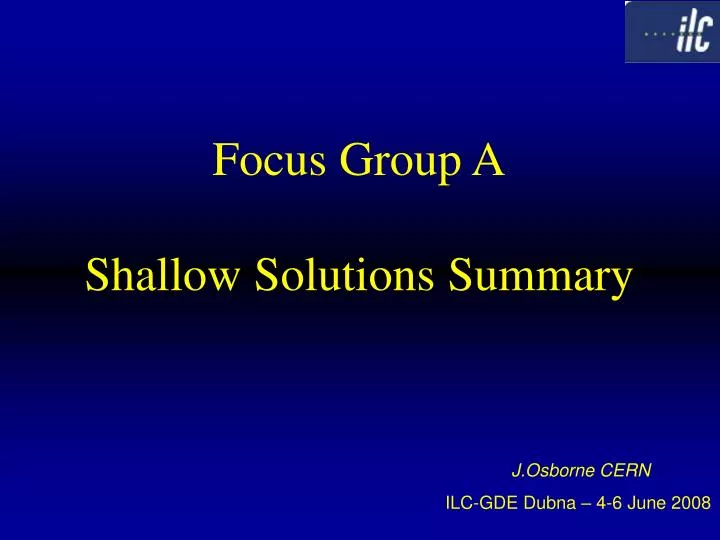
Focus Group A Shallow Solutions Summary. J.Osborne CERN ILC-GDE Dubna – 4-6 June 2008. All 3 samples site in RDR are for deep-tunnel solutions Shallow Sites are to be studied in this group, with emphasis on cost savings Possible sites : JINR, DESY, FNAL, Japan..

E N D
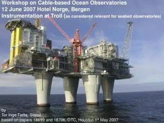
Focus Group AShallow Solutions Summary J.Osborne CERN ILC-GDE Dubna – 4-6 June 2008
All 3 samples site in RDR are for deep-tunnel solutions Shallow Sites are to be studied in this group, with emphasis on cost savings Possible sites : JINR, DESY, FNAL, Japan.. Tunnel configuration eg single tunnels such as XFEL, CLIC ILC-CLIC Collaboration Mandate
Dubna Shallow Site, including cost estimate Shallow site and Deep tunnel solutions Shallow Site Interaction Region Japan Sites CLIC single tunnel solution XFEL single tunnel solution Topics
Some Potential Cross-Sections Single Tunnel Single Tunnel Open Cut Open Cut Twin Enclosures Open Cut Twin Tunnels Braced Excavation
DUBNA Proposed typical cross section Beam tunnel 20m below surface Communication tunnel Vertical shaft vertical communication shaft -20,0 accelerator tunnel
To replace 20m deep TBM tunnel with on-surface gallery for services (following land contours) would be substantially cheaper Pre-cast concrete modules would be fabricated (planning advantages) Once site investigation reports are available, Dubna experts could execute detailed costing exercise in 2 to 3 months… Approx 10% saving on total CFS costs for replacing one bored tunnel with surface gallery Dubna Shallow Site
Possible layout for interaction region for a Shallow Site Near Surface Solution experimental hall approx. half the cost of a deep solution (for CERN sample site) + much less risk
Based on experience in Japan, it is not considered practical, mainly on cost grounds, to further investigate cut/cover option Hard rock tunnels only require ‘simple’ sprayed lining Very expensive to create a stable, horizontal tunnel on surface (piles and retaining walls required) Japan Sites
Comparison between TESLA & ILCSingleTunnel v Double Tunnel at DESYExtract ‘Parametric Measures’ W.Bialowons 5 June 2008 • However, RDR studies for shallow twin tunnel at DESY, came out more expensive than deep tunnels !!
XFEL The European X-Ray Laser Project X-Ray Free-Electron Laser XFEL Tunnel cross-section Duct for smoke removal Helium exhaust line Fire safe separation Lights Lights Alarm systems Cable trays Cryo- module Wave guides Phone Water for cooling towers & ‘normal’ fire fighting Survey trolley High pressure water for fire fighting Compressed air Cooling water 30°(ret.) Klystrons, racks, etc Survey marks Cooling water 18°(ret.) Transport & escape route Cooling water 18°(in) Channel for glass fibres Power cables Cooling water 30°(in) 10
XFEL Complicated floor / underfloor construction ‘Kerbs’ to close the gap towards tuebbings Floor slabs 1.2 x 1.9 x 0.25, 1.5 t Floating pre-casted high precision segments 1.20 m in Z Integrated channel for glass fibres In-situ mortar layer for gap filling towards tuebbing shell 11
Overall schedule 5 years from excavation to first beam for ≈ 3km machine Installation of underfloor services on critical path Difficult to access underfloor services once machine is installed XFEL The European X-Ray Laser Project X-Ray Free-Electron Laser XFEL Challenges
CLIC – Typical Cross Section The challenge is to fit all the services in the smallest underground volume, whilst respecting the relevant safety legislation
Possible Ventilation Systems for road tunnelsFor ‘uniform site which legislation do we adopt’ ? Extracted courtesy of ‘French Tunnelling Association : AFTES : Tunnels routiers : resistance au feu Jan 2008’
Integration of machine & services needed to define underground volumes A.Samoshkin 3D Clic module A.Kosmicki 3D Clic CE Turnaround area
Methods to compare various options incorporating both direct costs and the impacts on technical systems needs to be developed. Items such as reliability, complexity of installation and operations can be translated into a cost. An inclusive comparison can not be accomplished by CF&S alone. How far to develop the various option studies will need the guidance of Project Management and depend on the resources available. Deep twin tunnels, near surface and single tunnel options have been discussed for years. We need to conclusively resolve which options are feasible and provide the best value. This may require defining more than one “uniform site”. Ultimately Project Management will need to feel comfortable concurring with the analysis. Cost ComparisonExtract ‘Impact of 1 tunnel of Shallow Site’ 5 June 2008 T.Lackowski
Design / Cost Reduction / PIP Extracted from ‘Report from PM’ : 4 June 2006 N.Walker, M.Ross, A. Yamamoto
CLIC / ILC Collaborationfor CFS works Draft Mandate and Work Plan Working Group Convenors : C.Hauviller & John Osborne (CERN), V.Kuchler (FNAL) Presented at Collaboration meeting of 13 May 2008 at CERN
The following working groups already exist : The Conventional Facilities and Siting ‘CFS Team’ for ILC ‘Civil Engineering and Services’ CES for CLIC, based at CERN These groups work independently on the civil engineering and services side of both projects. However, it has been agreed that resources permitting, both groups will work together on areas of mutual interest for both projects, with participation from both sides at relevant meetings. Next CLIC CES meeting 11 June. CLIC Collaboration meeting in October 08. CLIC / ILC Collaboration for CFS Works
CLIC : Civil Engineering and Services (CES) WG CES Working Group Representatives : Civil Engineering and Chairman J.Osborne CLIC Link Person H.Braun Cooling and Ventilation CV J.Inigo-Golfin / C.Martel Electricity EL K.Kahle Survey SU H.Mainaud Durand Controls, Safety ASE T.Pettersson Horizontal Handling HE K.Kershaw Vertical Handling HE I.Ruehl CE Layouts and cross-sections A.Kosmicki / D.Parchet SC Link Person R.Trant ILC members V.Kuchler (FNAL), A.Enomoto (KEK) Monthly and ad-hoc meetings. Reporting to CLIC Technical Committee chaired by C.Hauviller.
Mandate :General Objective-Develop the existing layouts for the project from a civil engineering and technical services point of view, and work with the various actors towards a realistic design for the CDR in 2010.Specific responsibilities:-Work will concentrate on the tunnel cross section required to accommodate the machine and it’s services (e.g. ventilation, electricity, survey, controls, safety and handling equipment)-The overall layout for the civil engineering (surface buildings, injectors, turnaroud loops and accelerator tunnels) will be studied for the various energy ranges i.e. 500Gev, 1Tev and 3Tev.-Develop a layout for the interaction region.-Examine environmental aspects of the project.-Work together with ILC on areas of synergy.This group will report back to the CLIC Technical Committee. Regular meetings are planned for once a month on 2nd Wednesday of the month 2:30pm.First meeting 14 MayAd-hoc meetings on dedicated subjects eg EL 4 April, CV 29 April…. CLIC Civil Engineering and Services (CES) WG
Study Example : TBM technology advancements Meeting with TBM manufacturer scheduled for 19 June 2008 : Uniform Site discussions
CLIC – HVAC issues Monorail ? Are these water pipes big enough ? Floor stability issues need to be studied. Transversal Ventilation ?
ILC : Conventional Facilities and Siting (CFS) WG CFS Working Group Representatives : CERN J.Osborne FNAL V.Kuchler, E.Huedem, T.Lackowski, L.Hammond KEK A.Enomoto, M.Tanaka JINR G.Shirkov, G.Trubnikov Project Management : M.Ross, J.Carwardine, P. Garbincius….. Video Meetings every two week.
Study Example : ILC RDR Baseline Layouts for Interaction Region
Possible layout for ILC Interaction Region for Deep Tunnel Solution using CMS concept
The following working groups already exist : ‘Civil Engineering and Services’ for CLIC, based at CERN The ‘CFS Team’ for ILC These groups work independently on the civil engineering and services side of both projects. However, it has been agreed that resources permitting, both groups will work together on areas of mutual interest for both projects, including : Civil Engineering Studies Optimisation of Tunnel and Shaft diameters, distance between shafts (linked to safety) Overall layout of the machine and interaction region infrastructure Shallow site v Deep Tunnel Option Single Tunnel v Double Tunnel Safety issues such as emergency egress Environmental issues Etc. Other Infrastructure Cooling Water ? Power Distribution Air Handling Transport Issues Radiation simulations / shielding ? Etc. The progress of these working groups on areas of mutual interest will be reported at the ILC-GDE and CLIC Collaboration Meetings working towards CLIC CDR and ILC TDP Phase I in 2010. EU FP7 funding will accelerate the ILC studies CLIC / ILC Collaboration Mandate for CFS Works
Dubna solution looks very promising, but Site Investigation needed to allow detailed costing (using same RDR principles) CFS will develop ‘Requirement Matrix’ over coming months Ground rules need to be defined by PM team eg which solutions do we pursue the most given resource levels, which safety legislation do we adopt…..site stragey XFEL progress to be followed closely, particularly during installation phase 3d Integration studies for ILC need to developed to allow CFS to better determine underground volumes ILC/CLIC collaboration is a promising development in CFS field Conclusions