Download
1 / 1
10 likes | 142 Views
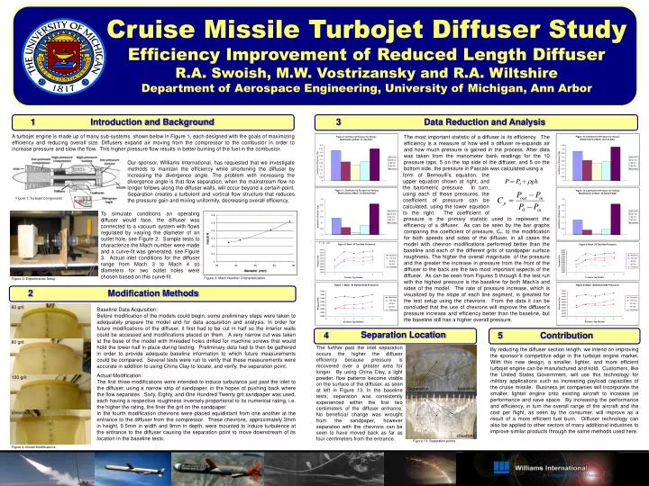
5. 4. 1. 2. 3. Cruise Missile Turbojet Diffuser Study Efficiency Improvement of Reduced Length Diffuser R.A. Swoish, M.W. Vostrizansky and R.A. Wiltshire Department of Aerospace Engineering, University of Michigan, Ann Arbor. Introduction and Background. Data Reduction and Analysis.

E N D
5 4 1 2 3 Cruise Missile Turbojet Diffuser Study Efficiency Improvement of Reduced Length Diffuser R.A. Swoish, M.W. Vostrizansky and R.A. Wiltshire Department of Aerospace Engineering, University of Michigan, Ann Arbor Introduction and Background Data Reduction and Analysis A turbojet engine is made up of many sub-systems, shown below in Figure 1, each designed with the goals of maximizing efficiency and reducing overall size. Diffusers expand air moving from the compressor to the combustor in order to increase pressure and slow the flow. This higher pressure flow results in better burning of the fuel in the combustor. The most important statistic of a diffuser is its efficiency. The efficiency is a measure of how well a diffuser re-expands air and how much pressure is gained in the process. After data was taken from the manometer bank readings for the 10 pressure taps, 5 on the top side of the diffuser, and 5 on the bottom side, the pressure in Pascals was calculated using a pressure is the primary statistic used to represent the efficiency of a diffuser. As can be seen by the bar graphs comparing the coefficient of pressure, Cp, to the modification for both speeds and sides of the diffuser, in all cases the model with chevron modifications performed better than the baseline and each of the different grits of sandpaper surface roughness. The higher the overall magnitude of the pressure and the greater the increase in pressure from the front of the diffuser to the back are the two most important aspects of the diffuser. As can be seen from Figures 5 through 8 the test run with the highest pressure is the baseline for both Mach’s and sides of the model. The rate of pressure increase, which is visualized by the slope of each line segment, is greatest for the test setup using the chevrons. From the data it can be concluded that the use of chevrons will improve the diffuser’s pressure increase and efficiency better than the baseline, but the baseline still has a higher overall pressure. Our sponsor, Williams International, has requested that we investigate methods to maintain the efficiency while shortening the diffuser by increasing the divergence angle. The problem with increasing the divergence angle is that flow separation, when the mainstream flow no longer follows along the diffuser walls, will occur beyond a certain point. Separation creates a turbulent and vortical flow structure that reduces the pressure gain and mixing uniformity, decreasing overall efficiency. form of Bernoulli’s equation, the upper equation shown at right, and the barometric pressure. In turn, using each of these pressures, the coefficient of pressure can be calculated, using the lower equation to the right. The coefficient of . Figure 1: Turbojet Components To simulate conditions an operating diffuser would face, the diffuser was connected to a vacuum system with flows regulated by varying the diameter of an outlet hole, see Figure 2. Sample tests to characterize the Mach number were made and a curve-fit was generated, see Figure 3. Actual inlet conditions for the diffuser range from Mach 3 to Mach 4 so diameters for two outlet holes were chosen based on this curve-fit. Figure 3: Mach Number Characterization Figure 2: Experimental Setup Modification Methods 60 grit Baseline Data Acquisition: Before modification of the models could begin, some preliminary steps were taken to adequately prepare the model and for data acquisition and analysis. In order for future modifications of the diffuser, it first had to be cut in half so the interior walls could be accessed and modifications placed on them. A very narrow cut was taken at the base of the model with threaded holes drilled for machine screws that would hold the lower half in place during testing. Preliminary data had to then be gathered in order to provide adequate baseline information to which future measurements could be compared. Several tests were run to verify that these measurements were accurate in addition to using China Clay to locate, and verify, the separation point. Actual Modification: The first three modifications were intended to induce turbulance just past the inlet to the diffuser, using a narrow strip of sandpaper, in the hopes of pushing back where the flow separates. Sixty, Eighty, and One Hundred Twenty grit sandpaper was used, each having a respective roughness inversely proportional to its numerical rating, i.e. the higher the rating, the finer the grit on the sandpaper. In the fourth modification chevrons were placed equidistant from one another at the entrance to the diffuser from the compressor. These chevrons, approximately 2mm in height, 0.5mm in width and 9mm in depth, were mounted to induce turbulence at the entrance to the diffuser causing the separation point to move downstream of its location in the baseline tests. Separation Location Contribution 80 grit The further past the inlet separation occurs the higher the diffuser efficiency because pressure is recovered over a greater area for longer. By using China Clay, a light powder, flow patterns become visible on the surface of the diffuser, as seen at left in Figure 13. In the baseline tests, separation was consistently experienced within the first two centimeters of the diffuser entrance. No beneficial change was wrought from the sandpaper, however separation with the chevrons can be seen to have moved back as far as four centimeters from the entrance. By reducing the diffuser section length, we intend on improving the sponsor’s competitive edge in the turbojet engine market. With this new design, a smaller, lighter, and more efficient turbojet engine can be manufactured and sold. Customers, like the United States Government, will use this technology for military applications such as increasing payload capacities of the cruise missile. Business jet companies will incorporate the smaller, lighter engine onto existing aircraft to increase jet performance and save space. By increasing the performance and efficiency, in turn the overall range of the aircraft and the cost per flight, as seen by the consumer, will improve as a result of a more efficient fuel burn. Diffuser technology can also be applied to other sectors of many additional industries to improve similar products through the same methods used here. 120 grit baseline Separation chevrons chevrons Figure 13: Separation points Figure 4: Model Modifications