Download
1 / 19
190 likes | 392 Views
FTU Real Time Control Overview. Magnetic Measurements probes ( 16 saddle + 16 pick-up coils) + DCN Interferometer. FTU. Electrical Power Supply ( feeding 4 sets of poloidal windings ) + Gas Injection System ( with 6 Piezoelectric valves ). The FTU Real Time Control.

E N D
Magnetic Measurements probes ( 16 saddle + 16 pick-up coils) + DCN Interferometer FTU Electrical Power Supply (feeding 4 sets of poloidal windings) + Gas Injection System (with 6 Piezoelectric valves) The FTU Real Time Control Measurement Systems Preprogrammed References (from CODAS) Controller Feedback System Actuating Systems
Gas Injection System
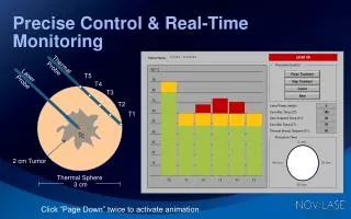
The FTU Real Time Control is dedicated to the control of the : • plasma current intensity • horizontal plasma position • vertical plasma position ( slight ) • gas density
Real Time controlled variables • Ip plasma current intensity • rint , rext internal and external radius • zlow , zup upper and lower boundary • ne electron density gas
Real Time actuating signals • IT T winding current (for Ip intensity control) • IF F winding current (for horiz. position plasma) • IH H winding current (for vert. position plasma) • Iv V winding current (to maintain the plasma in equilib. • 6 dig. signals fast valves ( for gas density ) )
Hardware Architecture VME BUS A D C #1 A D C #2 A D C #3 D A C T I M I N G RIO2 8062 (LynxOS) D A C IV, IF, IT, IH IpON (to the power supply system) D.I. FSC Signal Start-run Signal 6 on/off signals (for the 6 fast valves) CK=500 µs ne Saddle (16) Bpol (16) Ethernet
FTU CODAS Interface Vax 4000 Storage System (over AFS) Compaq Alpha (prometeo) pid,ran, limiter position, other scalar values Messages/replies Feedback data Feedback Measurements references
Feedback state diagram Storage request Idle Last shot data storage New Shot Abort Data from Codas Abort Prerun Off-line computation Start FSC Real-time control End-run
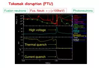
Real-Time duty cycle from -2s to +3s On/off (to the 6 valves) FTU Magnetic Measurements VLoop, IMagn, IP, Hard X ne IP ON F, T, V and H references CK A D C s D A C s Input Control law Output
Real-Time state evolution -1.5 -2.0 -1.4 -1.0 -0.001 +3.0 -0.01 A STATE B STATE C STATE D STATE E STAT. F STATE t (sec)
I N I N ELAB. ELAB. O U T O U T Control Loop wait wait t (sec) ~30µs ~5µs ~30µs0µs
Control Loop • From the A state to the E state (from -3.0 sec to -0.001 sec) • the elaboration is dedicated to calculate the • measurement offsets • toroidal magnetic component both to be removed during the F State • only the preprogrammed references are emitted
Control Loop F State (from -0.001 to +3 sec) • Measurements readout • offsets and toroidal component removal • plasma position computation • protections check (plasma presence, no disruption and no run-away) • PID control application • protections check (max amplitude and max derivative) • references emission
Conclusions • the FTU feedback system is: • fast and reliable • functionally satisfying • not very cheap ( cost of the whole system ~45000 € )