Download
1 / 7
70 likes | 164 Views
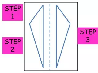
Step 1 - Load. Load the beam line or its sub components into your OSD session. Step 2 - Copy. Copy the entire assembly – this will insure that new system identifiers are issued for each of the components. Step 3 – Delete Original Model.

E N D
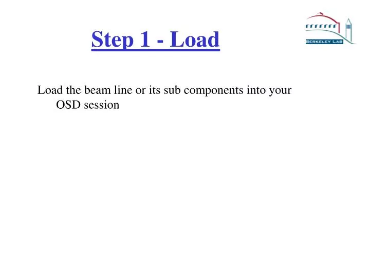
Step 1 - Load Load the beam line or its sub components into your OSD session
Step 2 - Copy Copy the entire assembly – this will insure that new system identifiers are issued for each of the components
Step 3 – Delete Original Model To prevent confusion delete the original model from your session. Note: Never again use the model that is stored on your U: drive always use the model checked into WorkManager.
Step 4 – Confirm Nomenclature Check to make sure that all of the assembly and part names conform to the ALS nomenclature scheme. Review the following 3 slides for a review of the ALS naming convention.
Model Naming Conventions 6 Rules: 1)All SolidDesigner part and assembly names are CAPITALIZED ex: BUILDING_ASSY VVR1_ASSY 2) Spaces between words are underscored ex: EXPERIMENTAL_FLOOR_ASSY VVR3_VALVE_STAND_ASSY 3) Hyphens are used between port numbers ex: 3-2-1_BRANCHLINE_FRONT_END_ASSY 3-2-2_HUTCH_ASSY 3-2-1_ENDSTATION_ASSY
Model Naming Conventions 6 Rules continued: 4) Each sector will have the following basic structure: ex: SECTOR_x_TOP_ASSY BUILDING_ASSY FRONT_END_ENVIRONMENT_ASSY EXPERIMENTAL_FLOOR_ASSY SECTOR_x_WALL_ASSY PORT_x-x_ASSY(S) 5) Beamline level assembly names start with a number (sector-port-branchline(s)) ex: 3-2-1_BRANCHLINE_FRONT_END_ASSY 3-2-2_HUTCH_ASSY 3-2-1_ENDSTATION_ASSY 6) Components below beamline level assemblies do NOT include the sector-port-branchline number. ex: PSS_ASSY VVR2_FAST_VALVE_ASSY Number is not included so that assemblies can be copied/shared to other beam lines and do not have to be renamed.
Model Naming Convention Summary Assy structure taken from WorkManager. • All Caps • Under scores between words • Hyphens between numbers • Sector assembly basic structure • Beam Line assy start with numbers; sector-port-branchline • Beam Line sub-assys named with descriptive names. These non beam line specific assemblies can be re-used on different beam lines with out re-naming. Note: Sector 3 used as an example.