Download
1 / 46
470 likes | 478 Views
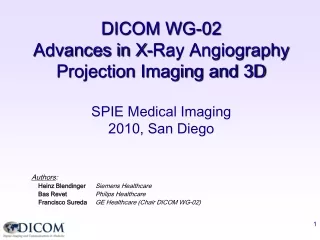
DICOM WG-02 Advances in X-Ray Angiography Projection Imaging and 3D SPIE Medical Imaging 2009, Orlando. Authors : Tim Becker European Society of Cardiology Heinz Blendinger Siemens Healthcare Bas Revet Philips Healthcare Francisco Sureda GE Healthcare (Speaker)

E N D
DICOM WG-02 Advances in X-Ray Angiography Projection Imaging and 3D SPIE Medical Imaging 2009, Orlando Authors: Tim Becker European Society of Cardiology Heinz Blendinger Siemens Healthcare Bas Revet Philips Healthcare Francisco Sureda GE Healthcare (Speaker) Rainer Thieme Siemens Medical Solutions (Chair DICOM WG-02)
Presentation Outline Introduction • Present and future of X-Ray Angiography in DICOM 2D Projection Images & Presentation • Application Cases of the Enhanced XA SOP Class • XA 2D Grayscale Softcopy Presentation State 3D Reconstruction from Projections & Presentation • X-Ray 3D SOP Class • N-Dimensional Grayscale Softcopy Presentation State Conclusion
Overview of X-Ray Angiography in DICOM Work in Progress Approved in the Standard X-Ray Acquisition Follow-up of PAS by IEC MT38 – 62B Supp 94: Radiation Dose Reporting Follow-up of IHE REM Profile 2D Projection Images Supp 139-PC: Enhanced XA Informative Annex Supp 83: Enhanced XA/XRF Supp 140-PC: Presentation State 3D Reconstruction Supp 116: X-Ray 3D Storage Multi-Dimensional Presentation State
Workflow 2D X-Ray Angiography SOP CLASS X-Ray 2D Projection SOP Class X-Ray Acquisition Procedure SOP CLASS 2D Presentation State SOP Class Presentation Procedure Visualization Visualization 2D Visualization System X-Ray Acquisition System
Enhanced XA: 2D projection images Supplement 83 – Standard 2004 • New SOP Class for Multi-frame X-Ray Projection Angiography • Re-use of encoding mechanisms of Enhanced CT and MR • Enhanced with new attributes to support new applications What can be done with this new SOP Class? • Supplement 139 (Part 17 – Informative) – Public Comments passed • Describes use cases where the Enhanced XA provides better solutions • Provides encoding guidelines for implementors, both creators and users of the Enhanced XA SOP Class
Enhanced XA: Supplement 139 X-Ray 2D Projection Enhanced XA SOP CLASS X-Ray Acquisition Modality Applications • General Definitions: • Time relationships, Acquisition Geometry, Pixel Size calibration • Application Use Cases • Acquisition: Waveform synch, Mechanical Movement, X-Ray controls… • Image Registration: 3D structures projected on 2D images • Display: Standard pipeline, multi-mask subtraction, per-frame pixel shift • Review: Variable review settings per group of frames • Processing: Projection pixel calibration
Enhanced XA – Time Relationships Frame “i” Acquisition Datetime Frame “N” Acquisition Datetime Frame “1” Acquisition Datetime (0018,9074) Content Date (0008,0023) Content Time (0008,0033) Frame “1” Reference Datetime (0018,9151) Acquisition Datetime (0008,002A) Frame “N” Reference Datetime Frame “i” Reference Datetime … … time FRAME N FRAME 1 FRAME i Frame “1” Acquisition Duration (0018,9220) Frame “N” Acquisition Duration Acquisition Duration (calculated) If Acquisition is synchronized with external time reference then Acquisition Time Synchronized (0018,1800) = YES Exposure Time (0018,9328) = SUMi( Frame “i” Acquisition Duration ) Average Pulse Width (0018,1154) = SUMi(Frame “i” Acquisition Duration) / N
Enhanced XA – Time Relationships (one frame) Frame Reference Datetime (0018,9151) Frame Acquisition Datetime (0018,9074) X-ray FRAME “i” Frame Acquisition Number (0020,9156) = “i” PRE-FRAME X-ray time Detector Activation Offset from Exposure (0018,7016) Frame Acquisition Duration (0018,9220) R Detector Active Time (0018,7014) Cardiac Trigger Delay Time (0020,9153) Last R-peak prior to the X-ray FRAME “i” T Q S NOTE: Positioner angle values, table position values etc… are measured at the Frame Reference Datetime
Enhanced XA – Acquisition Techniques Values per frame are in the Per-frame Functional Groups Seq.(200,9230): In the Frame Content Sequence(0020,9111): • Frame Acquisition Duration (0018,9220) in ms of frame « i » = Dti In the Frame Acquisition Sequence(0018,9417): • KVP (0018,0060) of frame « i = kVpi • X-Ray Tube Current in mA (0018,9330) of frame « i » = mAi
Enhanced XA – Acquisition Geometry System set up Image Transformation X-Ray Acquisition Pixel Data Storage PATIENT position on the Table FOV Rotation & Horiz Flip TABLE movement POSITIONER movement Detector Binning X-Ray Isocenter Reference System Macro X-Ray Geometry Macro Detector Description Patient Position Description X-Ray Table Description X-Ray Positioner Description FOV Description X-Ray Field of View Macro XA/XRF Acquisition Module • X-Ray Detector Module • Image Pixel Module
Enhanced XA – 3D/2D Registration Acquisition #1 Acquisition #2 +Zp +Xp +Yp +X +X +X +X +X +Z +Z +Z +Z +Z O O O O O +Y +Y +Y +Y +Y Table Movement Positioner Movement SID, ISO, FOV change P1 (x,y,z) P1t (xt,yt,zt) fa(P1, Table1) P2 (x,y,z) fb(P1t, Table2) P2p (xp,yp,zp) fc(P2, Positioner2) P2(i,j) fd(P2, SID, ISO, FOV)
Enhanced XA – Standard Display Pipeline Display VOI LUT P LUT Stored Values Pixel values transformed for specific application (if TO_LINEAR, then pixel values proportional to the X-ray beam intensity) Pixel Intensity Relationship LUT Application Pixel Intensity Relationship LUT Sequence (0028,9422) 1 to N Pixel values transformed for specific application Application Pixel Intensity Relationship LUT Pixel Intensity Relationship LUT Sequence (0028,9422) Shape = “IDENTITY” if (0028,0004) = MONOCHROME2 Shape = “INVERSE” if (0028,0004) = MONOCHROME1 X Modality LUT “TO_LINEAR” is required if Pixel Intensity Relationship (0028,1040) = LOG
Enhanced XA – Variable Review Settings 1 2 3 4 5 6 7 8 9 10 11 12 13 14 15 16 17 18 19 Acq. Frame rate: 15.0 Purpose: Contrast Media Acq. Frame rate: 8.0 Purpose: Contrast Media Acq. Frame rate: 4.0 Purpose: X-Ray control Item 1 >Start Trim (0008,2142) = 14 = 1 = 6 >Stop Trim (0008,2143) = 13 = 5 = 19 = DISPLAY = SKIP = DISPLAY >Skip Frame Range Flag (0008,9460) = 8.0 = 4.0 = 15.0 >Recom. Display Frame Rate (0008,9459) Item 2 >Start Trim (0008,2142) >Stop Trim (0008,2143) >Skip Frame Range Flag (0008,9460) > Recom. Display Frame Rate (0008,9459) Item 3 >Start Trim (0008,2142) >Stop Trim (0008,2143) >Skip Frame Range Flag (0008,9460) > Recom. Display Frame Rate (0008,9459) FRAME ACQUISITION: Frame Display Sequence (0018,7022) DICOM ENCODING: XA/XRF Multi-frame Presentation Module
Enhanced XA – Pixel Shift per frame = AVG_SUB = AVG_SUB = 101 = 100 = 2\3 = 2\3 = 1 = 1 = Right leg = Left leg Right Leg Left Leg Sub ID 101 Sub ID 100 Item 1 >Mask Operation (0028,6101) >Subtraction Item ID (0028,9416) >Applicable Frame Range (0028,6102) >Mask Frame Numbers (0028,6110) >Mask Operation Expl. (0028,6190) Item 2 >Mask Operation (0028,6101) >Subtraction Item ID (0028,9416) >Applicable Frame Range (0028,6102) >Mask Frame Numbers (0028,6110) >Mask Operation Expl. (0028,6190) FRAME ACQUISITION and PROCESSING: DICOM ENCODING: Mask Module Frames Mask Subtraction Sequence (0028,6100) #1 #2 #3
Enhanced XA – Pixel Shift per frame FRAME ACQUISITION and PROCESSING: DICOM ENCODING: Frame Pixel Shift per frame Frames Item 2 Frame #2 >Frame Pixel Shift Seq (0028,9415) #1 #2 Item 3 Frame #3 >Frame Pixel Shift Seq (0028,9415) #3
Enhanced XA – Pixel Shift per frame Left Leg = 100 = 100 = 2.0\10.0 = 0.0\8.0 Item 1 mask >>Subtraction Item ID (0028,9416) >>Mask Sub-pix Shift (0028,6114) Pixel Shift 0.0 \ 8.0 Item 1 Pixel Shift 2.0 \ 10.0 >>Subtraction Item ID (0028,9416) >>Mask Sub-pix Shift (0028,6114) FRAME ACQUISITION and PROCESSING: DICOM ENCODING: Frame Pixel Shift per frame Frames Item 2 Frame #2 >Frame Pixel Shift Seq (0028,9415) #1 #2 Item 3 Frame #3 >Frame Pixel Shift Seq (0028,9415) #3
Enhanced XA – Pixel Shift per frame Right Leg Left Leg = 100 = 100 = 101 = 0.0\8.0 = 0.0\-7.0 = 2.0\10.0 Item 1 mask mask >>Subtraction Item ID (0028,9416) >>Mask Sub-pix Shift (0028,6114) Item 2 >>Subtraction Item ID (0028,9416) = 101 Pixel Shift 0.0 \ 0.0 Pixel Shift 0.0 \ 8.0 = 0.0\0.0 >>Mask Sub-pix Shift (0028,6114) Item 1 Pixel Shift 0.0 \ -7.0 Pixel Shift 2.0 \ 10.0 >>Subtraction Item ID (0028,9416) >>Mask Sub-pix Shift (0028,6114) Item 2 >>Subtraction Item ID (0028,9416) >>Mask Sub-pix Shift (0028,6114) FRAME ACQUISITION and PROCESSING: DICOM ENCODING: Frame Pixel Shift per frame Frames Item 2 Frame #2 >Frame Pixel Shift Seq (0028,9415) #1 #2 Item 3 Frame #3 >Frame Pixel Shift Seq (0028,9415) #3
Enhanced XA - Projection Pixel Size Calibration D D = # Px * Px * SOD / SID #Px SOD = ISO - (TH - TO) / cos°(Beam Angle) Isocenter Beam Angle SID ISO D TH TO Table X - R ay Source How to convert from “image pixels” to “object mm in patient” #Px = Object size in “image” pixels D = Object size in mm TH = Table Height (0018,1130) TO = Dist. Table to Object (0018,9403) Beam Angle (0018,9449) SID = Dist. Source-Detector (0018,1110) ISO = Dist. Source-ISO (0018,9402) DPx = Imager Pixel Spacing (0018,1164)
Supplement 140: new XA GSPS IOD (for 2D) • Information that may be used to present angiographic projection images • It includes capabilities from the Grayscale Softcopy Presentation IOD for specifying: • a. the output grayscale space in P-Values • b. grayscale contrast transformations including VOI LUT • c. selection of the area of the image to display , rotate, flip • d. image and display relative annotations, graphics, text and overlays
Supplement 140: new XA GSPS IOD (for 2D) • Specific capabilities are provided for the presentation of angiographic projection images: • a. shutter specifications on a frame-by-frame base, • b. mask subtraction including regional pixel shift • c. presentation of sets of frames • Similar to the XA/XRF Multi-Frame Presentation Module of the Enhanced XA/XRF
XA Grayscale Softcopy Presentation State • Grayscale Contrast Transformations The sequence of transformations from stored pixel values into P-Values is explicitly defined in a conceptual model • Shutter per frame The shutter coordinates per-frame may be modified in post-review Frame #1 Frame #2 Frame #3 Frame #4 Frame #5
XA Grayscale Softcopy Presentation State mask subtraction & regional pixel shift If Pixel Intensity Relationship is not LOG « TO_LOG » LUT … Else VOI LUT SUB Contrast Frame(s) Pixel Shift & Anatomic Background Visibility Else « TO_LOG »LUT If Pixel Intensity Relationship is not LOG Mask Frame(s)
XA Grayscale Softcopy Presentation State Regional pixel shift Applicable pixel shift in case of multiple pixel shift regions
Sup 140 – Example of Regional Pixel Shift Mask frame:non-injected structures (bones, soft-tissues…)
Sup 140 – Example of Regional Pixel Shift Contrast frame:injected vessels – background structures moved since the mask acquisition
Sup 140 – Example of Regional Pixel Shift Subtraction without pixel shift:background structures are visible
Sup 140 – Example of Regional Pixel Shift Regional Pixel Shift:Select region 1
Sup 140 – Example of Regional Pixel Shift Mask Pixel Shift (Column) Mask Pixel Shift (Row) Regional Pixel Shift:Apply shift to mask on region 1
Sup 140 – Example of Regional Pixel Shift Mask Pixel Shift (Column) Mask Pixel Shift (Row)
Sup 140 – Example of Regional Pixel Shift Mask Pixel Shift (Column) Mask Pixel Shift (Row)
Sup 140 – Example of Regional Pixel Shift Mask Pixel Shift (Column) Mask Pixel Shift (Row) … until background structures are not visible anymore
Sup 140 – Example of Regional Pixel Shift Regional Pixel Shift:Select region 2
Sup 140 – Example of Regional Pixel Shift Mask Pixel Shift (Column) Regional Pixel Shift:Apply shift to mask on region 2
Sup 140 – Example of Regional Pixel Shift Regional Pixel Shift:Select region 3
Sup 140 – Example of Regional Pixel Shift Mask Pixel Shift (Column) Regional Pixel Shift:Apply shift to mask on region 3
Sup 140 – Example of Regional Pixel Shift Subtraction with regional pixel shift:background structures are not visible anymore
Workflow 3D X-Ray Angiography SOP CLASS SOP CLASS X-Ray 2D Projection SOP Class 3D Storage SOP Class X-Ray Acquisition Procedure Reconstruction Procedure In progress 3D Presentation State SOP Class Presentation Procedure X-Ray Calibration Procedure Calibration Data Proprietary Visualization Visualization X-Ray Acquisition System 3D Reconstruction System 3D Visualization System
X-Ray 3D Angiography Supplement 116 – In standard 2007 • New SOP Class for Multi-frame X-Ray 3D from projections • Re-use of encoding mechanisms of Enhanced CT and MR • Re-use volumic descriptions of Enhanced CT and MR • Additional information of the reconstruction from projections What can be done with this new SOP Class? • Basic 3D visualization (slices) • References to 2D projections • Description of the reconstruction application • Relationship to the Equipment Coordinate System • ...
X-Ray 3D Angiography – Rotational Acquisition Optimized 3D Reconstruction Frame #5: X-ray settings 5 Geometry settings 5 Frame #4: X-ray settings 4 Geometry settings 4 Frame #3: X-ray settings 3 Geometry settings 3 Frame #2: X-ray settings 2 Geometry settings 2 Frame #1: X-ray settings 1 Geometry settings 1
X-Ray 3D Angiography – Reference to 2D Mask Contrast Source #1: Contrib. SOP Inst = SOP Inst “A” M1... ...M2 C1... ...C2 Acq #1: Source Img Seq = A: M1 to M2 Reconstruction 1 Reconstruction 2 Acq #2: Source Img Seq = A: C1 to C2 Mask = 1 Recon #1: Acquisition Index SUB = 1\2 Recon #2: Acquisition Index 1... ...N N+1... ...N+k = 1 Frames #1 to #N: Recon Index = 2 Frames #N+1 to #N+k: Recon Index 2D Projection SOP Instance «A» Contributing SourcesSequence (0018,9506) SOP Instance description X-Ray 3D Acquisition Sequence (0018,9507) Acquisition description X-Ray 3D Reconstruction Sequence (0018,9530) Reconstruction description Per-Frame Func Groups Sequence (5200,9230) Frame description X-Ray 3D SOP Instance
X-Ray 3D Angiography - Relationship to Equipment Image to Equipment Matrix (0028,9520) Patient Oriented Coordinate System of the 3D slices Equipment Coordinate System of the 2D projections +X +Z P (Ax, Ay, Az) P (Bx, By, Bz) O +Y Enhanced XA: Isocenter Reference System
X-Ray 3D Angiography – Presentation State • Needs for 3D Angiography Presentation • Presentation features common to all 3D • Speficic presentation of X-Ray 3D Angiography: • Acquisition 3D shutter for collimation • Volume Subtraction and voxel shift • Stabilized point in all volumes (e.g. cardiac wall motion, stent stabilized) • Catheter tracking trajectory in one volume • 2D-3D blending presentation (3D conic projection on 2D fluoroscopy) • N-Dimensional Presentation State • Work Item 2008-04-C. Addresses needs of multi-modalities • Led by Working Group 11, participation of Web3D and other working groups • Supplement in progress...
Conclusion Supplement 139 – Enhanced XA application cases • In Public Comments. Informative (DICOM Part 17) • Will facilitate the adoption of the Enhanced XA (Sup 83) Supplement 140 – XA/XRF Presentation State • In Public Comments. Enables: • shutter on a frame-by-frame base, • mask subtraction including regional pixel shift • presentation of set of frames X-Ray 3D Angiography • New IOD approved in Standard 2007 (Sup 116) • 3D Presentation State on-going... Contact WG-02 chairman: francisco.sureda@med.ge.com