Download
1 / 18
180 likes | 189 Views
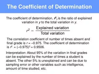
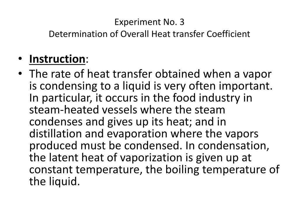
Experiment No. 3 Determination of Overall Heat transfer Coefficient. Instruction :

E N D
Experiment No. 3Determination of Overall Heat transfer Coefficient • Instruction: • The rate of heat transfer obtained when a vapor is condensing to a liquid is very often important. In particular, it occurs in the food industry in steam-heated vessels where the steam condenses and gives up its heat; and in distillation and evaporation where the vapors produced must be condensed. In condensation, the latent heat of vaporization is given up at constant temperature, the boiling temperature of the liquid.
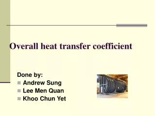
Steam condenser: • A shell and tube heat exchanger is a class of heat exchanger designs. It is the most common type of heat exchanger in oil refineries and other large chemical processes, and is suited for higher-pressure applications. As its name implies, this type of heat exchanger consists of a shell (a large pressure vessel) with a bundle of tubes inside it. One fluid runs through the tubes, and another fluid flows over the tubes (through the shell) to transfer heat between the two fluids. The set of tubes is called a tube bundle, and may be composed by several types of tubes: plain, longitudinally finned, etc.
A surface condenser is a commonly used term for a water-cooled shell and tube heat exchanger installed on the exhaust steam from a steam turbine in thermal power stations. These condensers are heat exchangers which convert steam from its gaseous to its liquid state at a pressure below atmospheric pressure. Where cooling water is in short supply, an air-cooled condenser is often used. An air-cooled condenser is however significantly more expensive and cannot achieve as low a steam turbine exhaust pressure as a water-cooled surface condenser.
Apparatus: • Steam boiler, Fulton three phase, 30 kW with all accessories including pressure upto 8 bar control of steam and water level inside the boiler for both low and high level water level, the boiler is supplied by safety valve and opens at pressure more than 10 bar. Multi-tube condenser fig(1). The top of the condenser (inlet) is fed with steam from the boilers main supply via an isolating valve through a reducing valve. The bottom of the condenser (outlet) is connected into a condensate measuring vessel. The metered cooling water flow to the condenser is arranged to cool the steam inside the condenser in the direct flow mode see fig.(2).
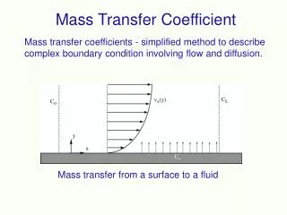
Figure (2) temperature distribution along the heat exchanger
Test procedure: • Operate the steam boiler for steam supply. • Start the cooling water through the condenser. • Adjust the outlet temperature from the condenser to obtain approximately 10oC temperature rise of cooling water when the condenser is supplied with steam. • Adjust the steam isolating valve to give a reasonable condensate flow rate when steady condition has been reached. • Start recording the temperature, the supply pressure, the cooling water discharge and the initial level of the outlet condensate while the stop watch is started. • Repeat the the recordings several times during the total time of the experiment except the level of the outlet condensate. • After a specified period of time, close the steam valve and measure the final level of the collected condensate. • Allow the cooling water to flow for five minutes to ensure the condenser cooling and then close it. • Turn off the boiler.
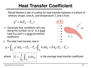
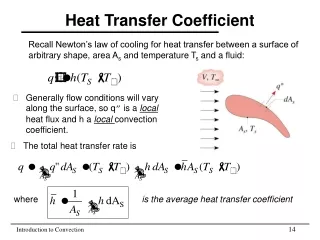
Theory: • The overall heat transfer coefficient is a measure of the overall ability of a series of conductive and convective barriers to transfer heat. It is commonly applied to the calculation of heat transfer in heat exchangers, but can be applied equally well to other problems. • The overall heat transfer coefficient takes into account the individual heat transfer coefficients of each stream and the resistance of the pipe material. In case of heat exchangers, U can be determined from the energy balance between the heat loss by the steam and the heat gain by the cooling water and follow the following governing equations. • Q (W) = U.A.T
In this case T is not constant over the whole area a mean temperature difference must be calculated since the temperature difference between cooled and cooling fluids in the condenser is not uniform through the equipment, and this quantity termed Logarithmic Mean Temperature difference used to enable simplified cooling calculation to be made.
But for steam the condensation occurs at constant temperature, so that T2=T3, so that
It is assumed that the flow conditions are stable and constant, the coefficient is constant along the tube and variations of properties of fluids concerned with temperature are small enough to be neglected.
1- Heat transfer equation. • U = Q / A.Tlmtd • Q rate of heat transfer, Watt • A total area of heat transfer, m2 • Tlmtd Logarithmic Mean Temperature Difference, oC. • U Overall heat transfer coefficient, W/m2.C . • Q = w.Cpw. (T5 – T4) • T5 cooling water final temperature, T4 cooling water initial temperature. The condenser consists of 19 [10.9 / 9.5 ] cylindrical tubes connecting flow tube plates of 76.2 mm diameter spaced 330.2 mm apart. • A = contacting area of tubes + contacting area of discs.
Table for experimental data: • A = (19**dm*330.3) + 2*
2- Velocity of Condensate • Velocity of condensate (m/s) = rate of volume condensate ( m3/sec) / A (m2)
Requirements: • What are the main types of condensers? Promote your answer with suitable sketches and specify the application of each type. • What is the effect of heat exchanger pipes configuration on heat transfer coefficient? • Write the main equations to find overall heat transfer coefficient for different situations and conditions.