Download
1 / 46
460 likes | 463 Views
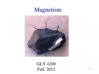
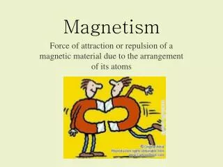
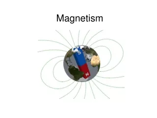
Magnetism 1. EM. Next Slide. Magnetism. Lodestone : naturally occurring mineral ore. For certain kind of substance, they attract irons and other special kinds of metal. Moreover, they have tendency to align themselves along N-S direction. Photo. North pole : the end always pointing north.

E N D
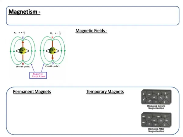
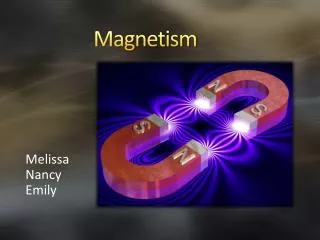
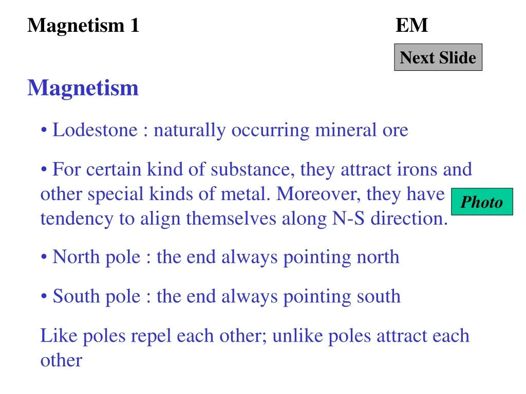
Magnetism 1 EM Next Slide Magnetism • Lodestone : naturally occurring mineral ore • For certain kind of substance, they attract irons and other special kinds of metal. Moreover, they have tendency to align themselves along N-S direction. Photo • North pole : the end always pointing north • South pole : the end always pointing south Like poles repel each other; unlike poles attract each other
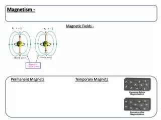
Magnetism 2 EM Next Slide Magnetic fields • Force experienced by iron exists near the magnet and is strongest near the poles. This is magnetic field. • Magnetic field lines : A compass aligns itself along the field lines near the magnet. • Common magnetic field patterns Diagram • Effect of magnetic field on iron powder and small compass Photo
Magnetism 3 EM Next Slide Magnetic effect of current • Magnetic field pattern due to a straight wire with current Diagram • Right-hand grip rule for direction of field Diagram • Solenoid and coil : circular wire with a number of turns Photo • Magnetic field pattern due to a solenoid with current Diagram • Right-hand grip rule for solenoid Diagram
Magnetism 4 EM Next Slide Electromagnets • Diagram for an electromagnet Diagram • Electromagnetic cranes • D.C. electric bells Photo • Ticker-tape timers Photo • Telephone communication Photo
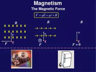
Left hand rule 1 EM Next Slide Fleming’s left hand rule • When a wire carrying a current is placed in a magnetic field, it experiences a force. • Fleming’s left hand rule Diagram • Loudspeaker Diagram • Turning effect on a coil in magnetic field Diagram • Simple d.c. motor Diagram
Left hand rule 2 EM Next Slide Applications • Practical motors Photo • Moving-coil galvanometer Photo • Change a galvanometer into an ammeter by a shunt resistor Diagram • Change a galvanometer into a voltmeter by a multiplier resistor Diagram • Multimeter Photo
Back to Magnetism 1 EM Click Back to • Some sample magnets are shown in the following photo.
small compass S N Magnetism 2 EM Next Slide • Magnetic field pattern of a bar magnet • The direction of field lines can be represented by a small north pole object, like the north pole of a small compass.
N S Back to Magnetism 2 EM Click Back to • Magnetic field pattern between two large poles
Magnetism 2 EM Next Slide • Effect on magnetic powder
Back to Magnetism 2 EM Click Back to • Effect on small compass
current flowing out of the paper current flowing into the paper Magnetism 3 EM Next Slide • Magnetic field pattern due to a straight wire
With current Without current Back to Magnetism 3 EM Click Back to • Effect of current in a straight wire on small compass
Direction of current Direction of magnetic field Back to Magnetism 3 EM Click Back to • Right-hand grip rule for direction of field • The right hand’s fingers grip in the direction of the field if the the thumb points to the same direction as the flow of current.
Back to Magnetism 3 EM Click Back to • Solenoid and coil
current field lines Back to Magnetism 3 EM Click Back to • Magnetic field of a solenoid with current
fingers indicate current direction N-pole S-pole Magnetism 3 EM Next Slide • Right-hand grip rule for solenoid • If the thumb of the right-hand points to the N-pole, the fingers would point to the direction of current flow in the coil.
fingers indicate current direction N-pole S-pole Back to Magnetism 3 EM Click Back to • Strength of magnetic field of a solenoid can be increased by. (i) increasing the current, and (ii) increasing the number of turns per unit length
current field lines soft iron Back to Magnetism 4 EM Click Back to • An electromagnet with soft iron-core’s field pattern :
Back to Magnetism 4 EM Click Back to • D.C. electric bells
Back to Magnetism 4 EM Click Back to • Ticker-tape timers
Back to Magnetism 4 EM Click Back to • Telephone communication
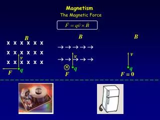
Force (F) Magnetic field (B) Current (I) Left hand rule 1 EM Next Slide • Fleming’s left hand rule : The thumb, the first finger and the second finger indicates the direction of force (F), magnetic field (B) and current (I) respectively if they are held perpendicular to each other. (FBI in short)
Current is flowing out of the paper Force N S Back to Left hand rule 1 EM Click Back to • Force experienced by the current-carrying conductor can be increased by (a) increasing the strength of the magnetic field, (b) increasing the size of the current, (c) increasing the length of the conductor.
magnet paper cone N N S N solenoid N electrical signal Left hand rule 1 EM Next Slide • Loudspeaker
magnet paper cone vibrates to produce sound Solenoid with paper cone is forced to vibrate due to the force in left hand rule electrical signal Back to Left hand rule 1 EM Click Back to • Varying alternating current passes through the coil.
N S Left hand rule 1 EM Next Slide • A coil with current flow is placed in a uniform field as shown in the following figure.
N S N S Left hand rule 1 EM Next Slide • When the plane of the coil is parallel to the field, the couple produced is greatest and the coil rotates clockwisely. • As the coil rotates, the perpendicular distance between the two forces becomes smaller and so the couple decreases.
N S N S Left hand rule 1 EM Next Slide • When the plane of the coil is perpendicular to the field, there is no couple. It still rotates clockwisely due to its inertia. • When the coil overshoot the vertical, anti-clockwise moment turns the coil back.
N S Back to Left hand rule 1 EM Click Back to • The coil, at last, oscillates about the vertical line.
Left hand rule 1 EM Next Slide • A simple d.c. motor contains a rectangular coil of many turns which can freely rotate about an axis. Uniform magnetic field which is produced by using two large magnets, passes through the coil. The ends of this coil contains two half-rings which are in contact with two small carbon brushes. The half-rings are called as commutators.
Left hand rule 1 EM Next Slide • Couple produced forces the coil to rotate clockwisely
Left hand rule 1 EM Next Slide • As the coil rotates, the turning couple decreases.
Left hand rule 1 EM Next Slide • When the coil passes the vertical line, the carbon brushes are in contact with the rings of the opposite sides. The direction of the current as well as the direction of the forces reverses. • The coil therefore carries on rotating clockwisely.
Back to Left hand rule 1 EM Click Back to • Turning effect on the coil and the simple d.c. motor can be increased by (a) increasing the flow of current (b) increasing the number of turns in the coil (c) increasing the strength of the magnetic field (d) increasing the area of the coil
Back to Left hand rule 2 EM Click Back to • Practical motor
Left hand rule 2 EM Next Slide • Moving-coil galvanometer
Back to Left hand rule 2 EM Click Back to • Sensitivity of a galvanometer can be increased by (a) using weaker hairsprings (b) increasing the number of turns in the coil (c) increasing the strength of the magnetic field (d) increasing the area of the coil • Full scale deflection current (f.s.d. current) is the current needed to deflect the pointer to the end of the scale.
shunt resistance galvanometer Left hand rule 2 EM Next Slide • An ammeter can be made by connecting a resistor in parallel with a galvanometer. This ammeter can measure larger current. • The resistor used in this case is called shunt resistance.
shunt resistance (S) 1 - 0.01 A = 0.99 A M N 1 A 10 mA Resistance = 5 Left hand rule 2 EM Next Slide A milliammeter has a resistance of 5 and a f.s.d. current of 10 mA. What is the value of the shunt resistance needed to convert the meter to measure currents up to 1 A? What is the resistance of the adapted meter?
Back to Left hand rule 2 EM Next Slide • We assume 1 A current passes the ammeter. • Current through the milliammeter = f.s.d. current = 0.01 A • Current through the shunt = (1 - 0.01) A = 0.99 A • p.d. across MN = 0.01 5 = 0.99 S • S = 0.101 • Resistance of the adapted ammeter = 0.1 (Why?)
galvanometer multiplierresistance B A Left hand rule 2 EM Next Slide • A voltmeter can be made by connecting a resistor in series with the galvanometer. • The resistor used in this case is called multiplier resistance.
Multiplier (R) 20 mA 5 B A p.d. = 10 V Left hand rule 2 EM Next Slide A milliammeter has a resistance of 5 and a f.s.d. current of 20 mA. What is the value of the mulitplier resistance needed to convert the meter to measure p.d. up to 10 V? What is the resistance of the adapted meter?
Back to Left hand rule 2 EM Next Slide • We assume 10 V p.d. is across the voltmeter. • Current through the multiplier and the galvanometer = f.s.d. current = 0.02 A • p.d. across AB = 10 V = 0.02 (R + 5) • R = 495 • Resistance of the adapted meter = 495 + 5 = 500
Back to Left hand rule 2 EM Next Slide • Multimeter