Download
1 / 8
80 likes | 86 Views
The work deals with the design and construction of a portable antenna for military operational vehicle. It involved the construction of the prototype of the designed dish, though the prototype was without a feed, as well as using mathematical models to obtain the parameters of the dish antenna by varying the diameter and depth of the dish as well as the frequency of operation of the antenna. It was observed from the result that as the frequency of the VSAT increases, the gain of the antenna also increases while the beam width, diameter and depth of the dish decrease. It was concluded that increase in frequency of operation of a dish antenna results in increase in gain and decrease in beam width, diameter and depth. Emmanuel George Whyte | Jerome Olajide Ibileke "Design and Construction of a Portable Antenna for Military Operational Vehicle" Published in International Journal of Trend in Scientific Research and Development (ijtsrd), ISSN: 2456-6470, Volume-3 | Issue-6 , October 2019, URL: https://www.ijtsrd.com/papers/ijtsrd29222.pdf Paper URL: https://www.ijtsrd.com/engineering/other/29222/design-and-construction-of-a-portable-antenna-for-military-operational-vehicle/emmanuel-george-whyte

E N D
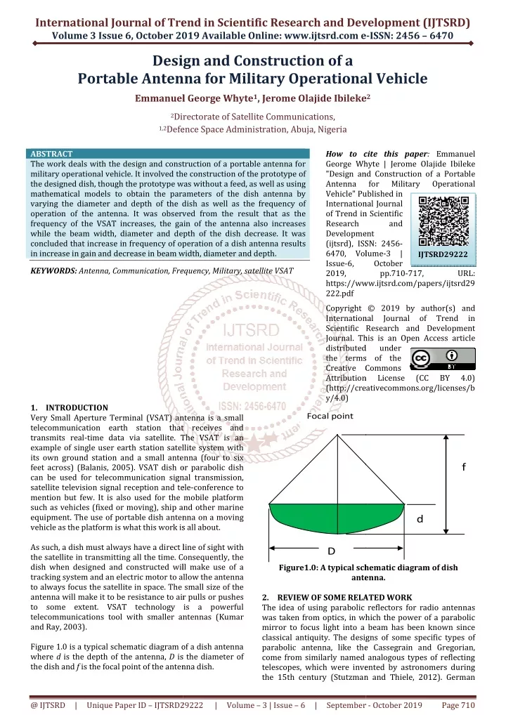
International Journal of Trend in Scientific Research and Development (IJTSRD) Volume 3 Issue 6, October 2019 2019 Available Online: www.ijtsrd.com e International Journal of Trend in Scientific Research and Development (IJTSRD) International Journal of Trend in Scientific Research and Development (IJTSRD) e-ISSN: 2456 – 6470 Design Design and Construction of a Antenna for Military Operational Vehicle Emmanuel George Whyte1, Jerome Olajide Ibileke Jerome Olajide Ibileke2 Portable Antenna f Emmanuel George Whyte or Military Operational Vehicle 2Directora 1,2Defence Space Administration, Abuja Defence Space Administration, Abuja, Nigeria Directorate of Satellite Communications, ABSTRACT The work deals with the design and construction of a portable antenna for military operational vehicle. It involved the construction of the prototype of the designed dish, though the prototype was without a feed, as well as using mathematical models to obtain the parameters of the dish antenna by varying the diameter and depth of the dish as well as the frequency of operation of the antenna. It was observed from the result that as the frequency of the VSAT increases, the gain of the antenna also increases while the beam width, diameter and depth of the dish decrease. It was concluded that increase in frequency of operat in increase in gain and decrease in beam width, diameter and depth. KEYWORDS: Antenna, Communication, Frequency, Military, satellite VSAT 1.INTRODUCTION Very Small Aperture Terminal (VSAT) antenna is a small telecommunication earth station that receives and transmits real-time data via satellite. The VSAT is an example of single user earth station satellite system with its own ground station and a small antenna (four to six feet across) (Balanis, 2005). VSAT dish or parabolic dish can be used for telecommunication signal transmission, satellite television signal reception and tele mention but few. It is also used for the mobile platform such as vehicles (fixed or moving), ship and other marine equipment. The use of portable dish antenna on a moving vehicle as the platform is what this work is all about. As such, a dish must always have a direct line of sight with the satellite in transmitting all the time. Consequently, the dish when designed and constructed will make use of a tracking system and an electric motor to allow the antenna to always focus the satellite in space. The small size of the antenna will make it to be resistance to air pulls or pushes to some extent. VSAT technology is a powerful telecommunications tool with smaller antennas (Kumar and Ray, 2003). Figure 1.0 is a typical schematic diagram of a dish antenna where d is the depth of the antenna, D is the diameter of the dish and f is the focal point of the antenna dish. is the focal point of the antenna dish. How to cite this paper: Emmanuel George Whyte | Jerome Olajide Ibileke "Design and Construction of a Portable Antenna for Military Vehicle" Published in International Journal of Trend in Scientific Research and Development (ijtsrd), ISSN: 2456- 6470, Volume-3 | 6, October 2019, pp.710-717, https://www.ijtsrd.com/papers/ijtsrd29 How to cite this paper George Whyte | Jerome Olajide Ibileke "Design and Construction of a Portab Antenna for Military Vehicle" Published in International Journal of Trend in Scientific Research and Development (ijtsrd), ISSN: 2456 6470, Volume Issue-6, October 2019, pp.710 https://www.ijtsrd.com/papers/ijtsrd29 222.pdf Copyright © 2019 by author(s) and International Journal Scientific Research and Development Journal. This is an Open Access article distributed under the terms of the Creative Commons Attribution License (http://creativecommons.org/licenses/b y/4.0) construction of a portable antenna for the construction of the prototype of the designed dish, though the prototype was without a feed, as well as using mathematical models to obtain the parameters of the dish antenna by varying the diameter and depth of the dish as well as the frequency of eration of the antenna. It was observed from the result that as the frequency of the VSAT increases, the gain of the antenna also increases while the beam width, diameter and depth of the dish decrease. It was concluded that increase in frequency of operation of a dish antenna results in increase in gain and decrease in beam width, diameter and depth. Operational Operational IJTSRD29222 Antenna, Communication, Frequency, Military, satellite VSAT URL: Copyright © 2019 by author(s) and International Journal Scientific Research and Development Journal. This is an Open Access article distributed under the terms of the Creative Commons Attribution License http://creativecommons.org/licenses/b of of Trend Trend in in (CC (CC BY BY 4.0) 4.0) Focal point Very Small Aperture Terminal (VSAT) antenna is a small telecommunication earth station that receives and time data via satellite. The VSAT is an example of single user earth station satellite system with its own ground station and a small antenna (four to six feet across) (Balanis, 2005). VSAT dish or parabolic dish f nal transmission, satellite television signal reception and tele-conference to mention but few. It is also used for the mobile platform such as vehicles (fixed or moving), ship and other marine equipment. The use of portable dish antenna on a moving e as the platform is what this work is all about. d As such, a dish must always have a direct line of sight with the satellite in transmitting all the time. Consequently, the dish when designed and constructed will make use of a ric motor to allow the antenna to always focus the satellite in space. The small size of the antenna will make it to be resistance to air pulls or pushes to some extent. VSAT technology is a powerful telecommunications tool with smaller antennas (Kumar D Figure1.0: A typical schematic diagram of dish antenna. antenna. SOME RELATED WORK The idea of using parabolic reflectors for radio antennas was taken from optics, in which the power of a parabolic mirror to focus light into a beam has been known since classical antiquity. The designs of some specific types of parabolic antenna, like the Cassegrain and Gregorian, come from similarly named analogous types of reflecting telescopes, which were invented by astronomers during the 15th century (Stutzman and Thiele, 2012). German chematic diagram of dish 2.REVIEW OF SOME RELATED WORK The idea of using parabolic reflectors for radio antennas was taken from optics, in which the power of a parabolic mirror to focus light into a beam has been known since classical antiquity. The designs of some specific types of parabolic antenna, like the come from similarly named analogous types of reflecting telescopes, which were invented by astronomers during the 15th century (Stutzman and Thiele, 2012). German Figure 1.0 is a typical schematic diagram of a dish antenna is the diameter of @ IJTSRD | Unique Paper ID – IJTSRD29 29222 | Volume – 3 | Issue – 6 | September 6 | September - October 2019 Page 710
International Journal of Trend in Scientific Research and Development (IJTSRD) @ www.ijtsrd.com eISSN: 2456-6470 III.Calculation of the area (A) of the dish: The area of the dish is also calculated as: D A = Physicist Heinrich Hertz constructed the world's first parabolic reflector antenna in 1888 (Stutzman and Thiele. 2012). The antenna was a cylindrical parabolic reflector made of zinc sheet metal and supported by a wooden frame. It also had a spark-gap excited dipole as a feed antenna along the focal line. Its aperture was 2 meters high by 1.2 meters wide, with a focal length of 0.12 meters, and was used at an operating frequency of about 450 MHz. With two such antennas, one used for transmitting and the other for receiving, Hertz demonstrated the existence of radio waves. This had been predicted by James Clerk Maxwell some 22 years earlier (Makino, 2006). However, the early development of radio was limited to lower frequencies at which parabolic antennas were unsuitable. They were also not widely used until after World War 2, when microwave frequencies began exploited. 3.METHODOLOGY This work is made up of the design of a complete dish antenna. The design is made up a complete dish or VSAT antenna consisting of the reflector and the feed which are done with step-by-step mathematical methods. The methodology for the design is as follows: 3.1.Mathematical computation method This involves the use of mathematical formulas to calculate the parameters of the dish antenna as well as the feed design. A.Reflector design: The procedures for the reflector or parabolic dish design are as follows. I.Calculation of the focal length (f) of the dish: The focal length of the dish can be determined using the value of the diameter, (D) and the depth, (d) of the dish. It is calculated using the formula given in equation 1. D f 16 Where D = Diameter of the dish, d = Depth of the dish and f = focal length of the antenna. This is when the diameter and the depth are known or chosen for the design. In a situation where the diameter and the focal length are already selected, then the dish depth is to be determined. The depth of the dish is determined using the formula given in equation 2 as; D d 16 Where D = Diameter of the dish, d = Depth of the dish and f = focal length of the antenna. II.Calculation of the ratio of the focal length (f) to the dish diameter (D), (f/D): The ratio, (f/D) is a standard value used for installation of the dish. It is calculated as: π 2 (4) 4 IV.Calculation of the gain, (G) of the antenna: The antenna gain is determined using; A 4 λ λ where A = Area of the dish, λ = wavelength and η= the efficiency of the antenna which is between 50% to 60% but 55% is used in this design. Equation (5) is the gain in watt (W) and equation (6) is the gain is decibel, (dB). V.Calculation of the beam width: the band width of the dish antenna is found using: λ 70 w = ηπ = G (5) 2 ηπ 4 A = G Log (6) 2 Beam idth (3.7) D Where λ = wavelength and D = Diameter of the dish. B.Feed Design A feed is one of the major components of a dish antenna as it performs active roles of receiving signal from the reflector and delivers it to the receiver, and receives signal or information from the transmitter and beams it unto a reflector for transmission. Reflector dish feed can be a horn antenna or an array of micro strip patch antennas. Although horn antenna has higher gain than micro strip antenna, the use of their array will increase the gain, less weight and reduced size. Thus, linear array feed will be designed for the work. Linear array feed A linear array feed is designed as a form of linear antenna array. Linear antenna array contains arrangement of antennas in a straight line. This work employs the use circular micro strip patch antenna array. It will also make use of six (6) antennas in a linear (1 x 6) form (i.e. one row, six columns) A micro strip antenna is composed of a metallic patch placed on a substrate or dielectric material. The steps for designing the feed are: I.Determination of the height (h) of the substrate: The height of the substrate is calculated using the formula: C h ε π 2 λ 2 where substrate, h is the height of the substrate. The dielectric material used in this design is TT DUROID type with 2.2, λ = wave length, c = speed of light wave and f = frequency of operation of the antenna. 2 = (1) d 2 = (2) f 0 3 . = (8) f r 0 3 . = h (9) π ε r rε is the dielectric constant of the dielectric f = Focal length diameter ratio (3) D rε = Where f = focal length of the dish and D = diameter. @ IJTSRD | Unique Paper ID – IJTSRD29222 | Volume – 3 | Issue – 6 | September - October 2019 Page 711
International Journal of Trend in Scientific Research and Development (IJTSRD) @ www.ijtsrd.com eISSN: 2456-6470 In this work, the frequency used for the design is 25GHz. Therefore, the wave length, λ, λ = C/f, (3 x 10⁸)/(25 x 109) = 0.012m. Now the h, in equation (3.9) transforms to: 012 . 0 3 . 0 x x where N = number of elements or antennas forming the array, n θ is the angle of illumination, d = distance between the antennas in the array, But λ = 0.012m = 1.2cm, 180o, N = 128o. When the parameters are substituted into equation 3.7, d = 0.22cm. Therefore, relating the inter-element distance with wave length, d = 0.2λ. The construction of the VSAT will be in prototype form. The dish will be constructed using one of the frequencies (25 GHz) used for the design above. It will also be constructed with local materials while the feed will be constructed using six array of a circular microstrip patch antenna in a linear form. Hardware Construction This involves the fabrication of the reflector or VSAT dish. The hardware construction in this work is limited to the reflector, excluding the feed. This is contained in the limitation for this thesis as earlier stated. The design of feed which is made up circular microstrip patch array is limited to the mathematical calculations of its parameters. Materials: The materials for the construction include aluminum, hark saw, mould, hearth, tape rule, and other minor materials. The aluminum metal was melted and poured inside a mould in which it took its shape when cooled. The shape of the mould which was made with a particular iron was according to the design parameters of the reflector which were gotten from mathematical computations. 4.RESULTS AND DISCUSSION The design of the antenna parameters such as gain, beam width and frequency to diameter ratio, f/D was carried out using the mathematical models. The processes involve varying the dish diameter and dish depth while keeping the frequency of operation constant. The diameter was varied from 0.2 m to 1.2 m with an increment of 0.2 meters, while the depth was also varied from 0.05 m to 1.20 m, with an increment of 0.01 meters, while the operating frequencies of 2.0, 2.5, 3.0, 3.5, 4.0, 4.5, 5.0, 15, 20 and 25 GHz were adopted for the chosen depths and diameters, taken one frequency at a time. A typical result of the modeling is presented in Table 1 for frequency of 2 GHz. Other results are presented in the appendixes for different frequencies. In addition, since size is the major concern especially as it will be mounted on a moving vehicle, the diameter of operation and beam width as well as the diameter and gain of the antenna were compared by series of plots. n θ = (10) x h = (11) 2 3 . 142 2 . 2 = 0.0003862m = 0.0386cm = 0.386mm II.Determination of physical radius of the circular patch, a. (12) 1 F = a 1 / 2 π 1 2 h F + + 1 ln . 1 7726 πε 1 2 h F r 9 . 8 791 10 x ε = 1 F But (13) f r When substituted, a = 0.22cm respectively. III.Determination of the beam width or aperture illumination: The beam width or aperture illumination is given as; = 1 16 D But from our previous calculations, F/D is 0.4. Thus, when F/D is substituted into equation (3.15), will equal to 128o. IV.Determination of inter-element distances. The formula for calculating the inter-element distance according to Balanis (2005) is: Nd 2 1 F = 0.2371 and F F 8 (14) D − θ 1 2 tan n 2 − θ m π λ − θ = − 1 2 Cos (15) n In a simplified form, the distance can be estimated using: λ = d (16) θ n sin N 2 Table1: A typical result of the Modeling At frequency of 2GHz with varying depth, d and diameter, D. D (m) d (m) F =D^2/16d Effi F (GHz) 0.2 0.05 0.050 0.55 2 0.4 0.06 0.167 0.55 2 0.6 0.07 0.321 0.55 2 0.8 0.08 0.500 0.55 2 1.0 0.09 0.694 0.55 2 1.2 0.1 0.900 0.55 2 Area 0.03 0.13 0.28 0.50 0.79 1.13 Gain (W) 9.65 38.61 86.88 154.44 241.32 347.50 Beam width 52.50 26.25 17.50 13.13 10.50 8.75 Gain (dB) 9.85 15.87 19.39 21.89 23.83 25.41 @ IJTSRD | Unique Paper ID – IJTSRD29222 | Volume – 3 | Issue – 6 | September - October 2019 Page 712
International Journal of Trend in Scientific Research and Development (IJTSRD) @ www.ijtsrd.com eISSN: 2456-6470 The matlab simulation results of the portable very small aperture terminal antenna with notched character are presented. Figure 2 shows the simulated impedance beam width as a function of antenna diameter. It can be observed that the beam width of the antenna is inversely proportional to the antenna frequency. As the frequency of operation is increased, the antenna beam width reduces. A typical plot showing the variation of antenna beam width with frequencies at antenna diameters of 0.2 and 1.2 m is presented in Figure 2. Operating frequencies of 2.0, 2.5, 3.0, 3.5m, 4.0, 4.5, 5.0, 15, 20 and 25GHz, were used for these depths and diameters, with one frequency at a time. The result shows that, as the diameter is increasing, the gain is decreasing and the beam width is increasing, but when the diameter is decreasing, the reverse is the case. However, the reduction in gain can be minimized or eliminated using space diversity method as well as having an array of the small dish. From the figure, it can be observed that the gain of the antenna is directly proportional to the antenna frequency while in terms of beam width, it is inversely proportional. 60.0 2 GHz 50.0 2.5 GHz 3 GHz 40.0 Beamwidth (dB) 3.5 GHz 30.0 4 GHz 4.5 GHz 20.0 10 GHz 10.0 15 GHz 20 GHz 0.0 0 0.2 0.4 0.6 0.8 1 1.2 1.4 25 GHz Diameter (m) Figure2: Influence of antenna diameters on antenna beam width at different frequencies 60.0 50.0 0.2 m diameter Beam width (dB) 40.0 30.0 20.0 10.0 0.0 0 5 10 15 20 25 30 Frequency (GHz) Figure3: Simulation of beam width of the proposed antenna Figure 4 shows the simulated gain curve as the function of antenna diameters based on different frequencies. The gain variation of this antenna in operating bandwidth is from 9.8 dBi to 32.2 dBi for antenna diameter of 0.2 m, and from 25.4 to 47.7 dBi for the antenna diameter of 1.2 mover the entire frequency range. It can also be seen that the gain of the antenna is directly proportional to the antenna frequency and antenna diameter. As the frequency of operation is increased, the antenna gain also increases. The result of applying a notch to create a rejected band is presented in Figure 4. It could be seen that the gain reduction is about 10.2 and 20.4 dBi at antenna diameters of 0.2 and 1.2 m respectively at 4GHz frequency. @ IJTSRD | Unique Paper ID – IJTSRD29222 | Volume – 3 | Issue – 6 | September - October 2019 Page 713
International Journal of Trend in Scientific Research and Development (IJTSRD) @ www.ijtsrd.com eISSN: 2456-6470 The results of the return loss and beam width as a function of antenna diameters are shown in Figure 6. It has been deduced for voltage standing wave ratio (VSWR) less than 2 and greater than 2. VSRW affects the impedance matching more significantly at higher frequencies than at lower frequencies. 60.0 2 GHz 50.0 2.5 GHz 40.0 Gain (dBi) 3 GHz 3.5 GHz 30.0 4 GHz 20.0 4.5 GHz 10 GHz 10.0 15 GHz 0.0 20 GHz 0 0.5 1 1.5 Diameter (m) Figure4: Simulated gain curve as the function of antenna diameters based on different frequencies. 60.0 ref at 0.2 m diameter Ref at 1.2 m diameter 50.0 40.0 30.0 Gain (dBi) 20.0 10.0 0.0 0 5 10 15 20 25 30 -10.0 -20.0 -30.0 Frequency (GHz) Figure5: Simulation with a notch to create a rejected band at 4 GHz frequency. 20 15 10 VSWR < 2 Return loss (dB) 5 0 -5 -10 -15 0 10 20 30 Frequency (GHz) Figure6: Return losses as function of antenna diameters. @ IJTSRD | Unique Paper ID – IJTSRD29222 | Volume – 3 | Issue – 6 | September - October 2019 Page 714
International Journal of Trend in Scientific Research and Development (IJTSRD) @ www.ijtsrd.com eISSN: 2456-6470 Hardware Construction Plates 1.0 shows the prototype of the dish antenna. The antenna was constructed using aluminum material due to its light weight and resistance to corrosion. The dimension of the constructed prototype is 40 cm diameter and 6 cm depth. The dish will have the focal length of 0.167 m and the f/d ratio of 0.417 m. The dish was constructed without the feed, which is a limitation of the work. REFERENCES [1]AkshayPrakash, Bernard (2014); ‘Analysis of double stub tuner control stability in a phased array antenna with strong cross-coupling. Fusion Engineering and Design, Volume 89, Issue, 3, pp. 2566-2577. [2]Constantine A. Balanis,(2016); Antenna theory, analysis and design (Fourth Edition), US: John Wiley & Sons. [3]Ersin Aras (2002); “Analysis of Jammer Resistant, Spread Spectrum, VSAT Communication scheme for maritime platform using 2002”,M.Sc Thesis in System Engineering, from Naval Postgraduate School. DS-CDMASeptember [4]Ibigbami Nelson O. and Adediran Y. A., (2011); “Performance Analysis of a Patch Antenna Array Feed for aSatellite C-Band Dish Antenna” Cyber Journals: Multidisciplinary Journals in Science and Technology, Journal Telecommunications (JSAT), November Edition, 2011, pp. 24-30 of Selected Areas in [5]KirtiChaurasiya and Satish Kumar (2015); “Design and Analysis of Parabolic Reflector Antenna using MATLAB” International Journal of Advanced Research in Electrical, Electronics Engineering. Vol. 4, Issue 3, pp. 1367-1377. and Instrumentation [6]Kumar, G. and Ray, K.P.,2003: Broadband Microstrip Antennas, Artech House Antennas and Propagation library) Inc. Technology and Engineering, Norwood MA pp.3-7. [7]Lehpamer, Harvey (2010). Microwave transmission networks: Planning, Design, and Deployment. USA: McGraw Hill Professional.Jun 22, 2010 - Technology & Engineering - 496 Plate 1.0: Photo of side view of the prototype of reflector dish (without feed) 5.CONCLUSION The design of a small sized VSAT has been done using mathematical models. The design was done by varying the diameter and depth of the dish. In the process, the frequency of operation was varied from 2 GHz to 25 GHz. In addition, the simulation of the radiation pattern of the dish antenna at frequencies 2, 2.5, 3, 3.5, -… 10, 15, 20 and 25 GHz were done using Matlab simulation. From the results, it was observed that as the frequency of operation of the antenna increases, the gain of the antenna increases while the beam width decreases. It can then be concluded that the frequency of operation of the dish is directly proportional to the gain of the antenna and inversely to the beam width, thus a decrease in beam width allows the signal sent to be directed towards a target and signal loss will be reduced. It can also be concluded that the higher the frequency, the smaller the size of the dish. 6.Recommendations The design of the dish and its feed has been done using mathematical method, and the construction of the prototype of the dish was done at the frequency of 25 GHz. The prototype was without a feed (which was just designed using microstrip patch antenna but not constructed), it is hereby recommended that the feed prototype construction be looked into as future work. [8]LiuChuan; Shiwen Yang; ZaipingNie(2013); “Design of a parabolic reflector antenna with a compact splash-plate feed” in IEEE Cross Strait Quad- Regional Radio Science and Wireless Technology Conference (CSQRWC), China. [9]Makino Shigero (2006); “Historical review of Reflector Antenna Systems Developed for Satellite Communications by Symposium on Antennas and Propagation — ISAP 2006, pp. 1-4. “MELCO” International [10]OlverA. D, P. J. B., Clarricoats A. A., Kishk L. Shafai 1994, Microwave Horns Electromagnetic Wave London U.K.:Inst. Elect.Eng. vol 39. and Feeds ser. [11]OmotoshoAdebayoand (2011): “Application of Constant Redial Model for Traffic Optimization in GSM: Traffic and channels control in mobile ”Saarbrucken, Germany, 3639374509 9783639374506. Justice Emuoyibofarhe wireless Communications Germany, ISBN: [12]PrabhakarTelagarapu, Lakshmi Prasanthi, VijayaSanthiG., B. Ravi Kiran(2011); Design and Analysis of Parabolic Reflector with High Gain Pencil Beam and Low side lobes by Varying feed, Int. J. Advanced Networking and Applications, Volume: 03, Issue: 02, Pages: 1105-1115. @ IJTSRD | Unique Paper ID – IJTSRD29222 | Volume – 3 | Issue – 6 | September - October 2019 Page 715
International Journal of Trend in Scientific Research and Development (IJTSRD) @ www.ijtsrd.com eISSN: 2456-6470 Appendix Modeling results for various frequencies Appendix1: Frequency of 2.5 GHz with varying depth, d and diameter, D D(m) d (m) F= D^2/16d Effi Freq (GHz) Area Gain (W) Beam width Gain (dB) 0.2 0.05 0.050 0.55 2.5 0.4 0.06 0.167 0.55 2.5 0.6 0.07 0.321 0.55 2.5 0.8 0.08 0.500 0.55 2.5 1.0 0.09 0.694 0.55 2.5 1.2 0.1 0.900 0.55 2.5 Appendix2: Frequency of 3 GHz with varying depth, d and diameter, D D(m) d (m) F= D^2/16d Effi Freq (GHz) Area Gain (W) Beam width Gain (dB) 0.2 0.05 0.050 0.55 3 0.4 0.06 0.167 0.55 3 0.6 0.07 0.321 0.55 3 0.8 0.08 0.500 0.55 3 1.0 0.09 0.694 0.55 3 1.2 0.1 0.900 0.55 3 Appendix 3: Frequency of 3.5 GHz with varying depth, d and diameter, D D (m) d (m) F= D^2/16d Effi Freq (GHz) Area Gain (W) Beam width Gain (dB) 0.2 0.050 0.050 0.55 3.5 0.4 0.060 0.1667 0.55 3.5 0.6 0.070 0.321 0.55 3.5 0.8 0.080 0.500 0.55 3.5 1.0 0.090 0.694 0.55 3.5 1.2 0.100 0.900 0.55 3.5 Appendix 4: Frequency of 4 GHz with varying depth, d and diameter, D D(m) d (m) F= D^2/16d Effi Freq (GHz) Area Gain (W) Beam width Gain (dB) 0.2 0.05 0.050 0.55 4 0.4 0.06 0.167 0.55 4 0.6 0.07 0.321 0.55 4 0.8 0.08 0.500 0.55 4 1.0 0.09 0.694 0.55 4 1.2 0.1 0.900 0.55 4 Appendix 5: Frequency of 4.5 GHz with varying depth, d and diameter, D D(m) d (m) F= D^2/16d Effi Freq (GHz) Area Gain (W) Beam Width Gain (dB) 0.2 0.050 0.050 0.55 4.5 0.4 0.060 0.167 0.55 4.5 0.6 0.070 0.321 0.55 4.5 0.8 0.080 0.500 0.55 4.5 1.0 0.090 0.694 0.55 4.5 1.2 0.100 0.900 0.55 4.5 Appendix 6: Frequency of 10 GHz with varying depth, d and diameter, D D(m) d (m) F= D^2/16d Effi Freq (GHz) Area Gain (W) Beam width Gain (dB) 0.2 0.050 0.050 0.55 10 0.4 0.060 0.167 0.55 10 0.6 0.070 0.321 0.55 10 0.8 0.080 0.500 0.55 10 1.0 0.090 0.690 0.55 10 1.2 0.100 0.900 0.55 10 0.03 0.13 0.28 0.50 0.79 1.13 15.08 60.33 135.74 241.32 377.06 542.97 42.00 21.00 14.00 10.50 8.40 7.00 11.78 17.81 21.33 23.83 25.76 27.35 0.03 0.13 0.28 0.50 0.79 1.13 21.72 86.88 195.47 347.50 542.97 781.88 35.00 17.50 11.67 8.75 7.00 5.83 13.37 19.39 22.91 25.41 27.35 28.93 0.03 0.13 0.28 0.50 0.79 1.13 29.56 118.25 266.05 472.99 739.04 1064.22 30.00 15.00 10.00 7.50 6.00 5.00 14.71 20.73 24.25 26.75 28.69 30.27 0.03 0.13 0.28 0.50 0.79 1.13 38.61 154.44 347.50 617.78 965.28 1390.00 26.25 13.13 8.75 6.56 5.25 4.38 15.87 21.89 25.41 27.91 29.85 31.43 0.03 0.13 0.28 0.50 0.79 1.13 48.87 195.47 439.80 781.88 1221.68 1759.22 23.33 11.67 7.78 5.83 4.67 3.89 16.89 22.91 26.43 28.93 30.87 32.45 0.03 0.13 0.28 0.50 0.79 1.13 241.32 965.28 2171.88 3861.11 6032.99 8687.50 10.50 5.25 3.50 2.63 2.10 1.75 23.83 29.85 33.37 35.87 37.81 39.39 @ IJTSRD | Unique Paper ID – IJTSRD29222 | Volume – 3 | Issue – 6 | September - October 2019 Page 716
International Journal of Trend in Scientific Research and Development (IJTSRD) @ www.ijtsrd.com eISSN: 2456-6470 Appendix 7: Frequency of 15 GHz with varying depth, d and diameter, D D(m) d (m) F= D^2/16d Effi Freq (GHz) Area Gain (W) Beam width Gain (dB) 0.2 0.05 0.05 0.55 15 0.4 0.06 0.1667 0.55 15 0.6 0.07 0.321 0.55 15 0.8 0.08 0.5 0.55 15 1.0 0.09 0.694 0.55 15 1.2 0.1 0.9 0.55 15 Appendix 8: Frequency of 20 GHz with varying depth, d and diameter, D D(m) d (m) F= D^2/16d Effi Freq (GHz) Area Gain (W) Beam width Gain (dB) 0.2 0.05 0.050 0.55 20 0.4 0.06 0.1667 0.55 20 0.6 0.07 0.321 0.55 20 0.8 0.08 0.500 0.55 20 1.0 0.09 0.694 0.55 20 1.2 0.1 0.900 0.55 20 Appendix 9: Frequency of 25 GHz with varying depth, d and diameter, D D(m) d (m) F= D^2/16d Effi Freq (GHz) Area Gain (W) Beam width Gain (dB) 0.2 0.050 0.050 0.6 25 0.4 0.060 0.167 0.6 25 0.6 0.070 0.321 0.6 25 0.8 0.080 0.500 0.6 25 1.0 0.090 0.694 0.6 25 1.2 0.100 0.900 0.6 25 0.03 0.13 0.28 0.50 0.79 1.13 542.97 2171.88 4886.72 8687.50 13574.23 19546.88 7.00 3.50 2.33 1.75 1.40 1.17 27.35 33.37 36.89 39.39 41.33 42.91 0.03 0.13 0.28 0.50 0.79 1.13 965.28 3861.11 8687.50 15444.45 24131.96 34750.02 5.25 2.63 1.75 1.31 1.05 0.88 29.85 35.87 39.39 41.89 43.83 45.41 0.03 0.13 0.28 0.50 0.79 1.13 1645.36 6581.44 14808.25 26325.77 41134.02 59232.98 4.20 2.10 1.40 1.05 0.84 0.70 32.16 38.18 41.71 44.20 46.14 47.73 @ IJTSRD | Unique Paper ID – IJTSRD29222 | Volume – 3 | Issue – 6 | September - October 2019 Page 717