Download
1 / 4
40 likes | 43 Views
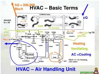
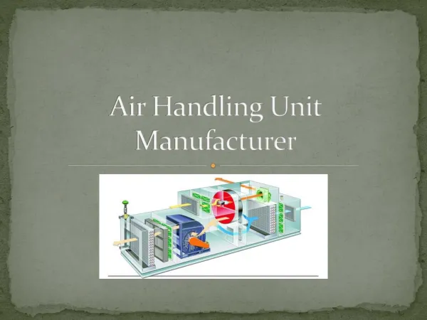
An Air Handling Unit is a central air conditioner station that handles the air that usually, will be supplied into the buildings by the ventilation ductwork connecting to it. Handling the air means that the air will be delivered into the building spaces with thermo hygrometric and Indoor Air Quality treatment. An Air Handling Unit is a large piece of equipment that alters the temperature and pressure of air being distributed throughout the building. Air Handling Unit is usually located in the ceiling or at the top of the building. In this project the building required to be air conditioned is designed and the necessary electrical accessories are placed in the design calculation of loads by using Revit software. The building is divided into spaces and zones through which a heat load calculation report is generated in the software. As per the peak cooling load generated in the report the air terminals and diffusers are placed in the required spaces and zones. The air terminals and diffusers are interconnected and these are connected to the Air Handling Unit. Basavaraja. Kt | G. Hema Satish Babu | G. Sai Reddy | E. Teja | B. Sai Krishna "Design of an Air Conditioning System for a Commercial Building using Air Handling Unit" Published in International Journal of Trend in Scientific Research and Development (ijtsrd), ISSN: 2456-6470, Volume-4 | Issue-1 , December 2019, URL: https://www.ijtsrd.com/papers/ijtsrd29454.pdf Paper URL: https://www.ijtsrd.com/engineering/mechanical-engineering/29454/design-of-an-air-conditioning-system-for-a-commercial-building-using-air-handling-unit/basavaraja-kt<br>

E N D
International Journal of Trend in Scientific Research and Development (IJTSRD) Volume 4 Issue 1, December 2019 Available Online: www.ijtsrd.com e-ISSN: 2456 – 6470 Design of an Air Conditioning System for a Commercial Building using Air Handling Unit Basavaraja. Kt1, G. Hema Satish Babu2, G. Sai Reddy2, E. Teja2, B. Sai Krishna2 1Assistant Professor, 2UG Scholar, 1,2Department of Mechanical Engineering, Guru Nanak Institute of Technology, Rangareddy, Telangana, India ABSTRACT An Air Handling Unit is a central air conditioner station that handles the air that usually, will be supplied into the buildings by the ventilation ductwork connecting to it. Handling the air means that the air will be delivered into the building spaces with thermo- hygrometric and Indoor Air Quality treatment. An Air Handling Unit is a large piece of equipment that alters the temperature and pressure of air being distributed throughout the building. Air Handling Unit is usually located in the ceiling or at the top of the building. In this project the building required to be air conditioned is designed and the necessary electrical accessories are placed in the design calculation of loads by using Revit software. The building is divided into spaces and zones through which a heat load calculation report is generated in the software. As per the peak cooling load generated in the report the air terminals and diffusers are placed in the required spaces and zones. The air terminals and diffusers are interconnected and these are connected to the Air Handling Unit. KEYWORDS: Heating, Ventilation, and Air-Conditioning (HVAC), Air Handling Unit, Refrigeration cycle, Heat load estimation How to cite this paper: Basavaraja. Kt | G. Hema Satish Babu | G. Sai Reddy | E. Teja | B. Sai Krishna "Design of an Air Conditioning System for a Commercial Building using Air Handling Unit" Published in International Journal of Trend in Scientific Research and Development (ijtsrd), ISSN: 2456- 6470, Volume-4 | Issue-1, December 2019, pp.192-195, https://www.ijtsrd.com/papers/ijtsrd29 454.pdf Copyright © 2019 by author(s) and International Journal of Trend in Scientific Research and Development Journal. This is an Open Access article distributed under the terms of the Creative Commons Attribution License (CC (http://creativecommons.org/licenses/by /4.0) IJTSRD29454 URL: BY 4.0) I. The average summer temperatures experienced by most countries are increasing every year and consequently the energy needs to provide air-conditioning is also increasing annually. The HVAC industry has a challenging task of providing energy efficient technologies to satisfy this growing demand with a minimum impact on global warming and ozone depletion. The air-conditioning system efficiency is very important as it determines the amount of energy that is being consumed for heating and or cooling. Many countries are creating minimum efficiency grades, to ensure that the HVAC industry continually strives towards the development of more efficient systems, thereby reducing the demands of energy. The increasing buying power of consumers globally is also generating a large demand for the development of air- conditioning systems that provide a higher level of comfort than that provided by the standard fixed capacity systems. The control of properties of air to suit the physiological requirements of the human body or to assist in improvement of the quality of industrial process is known as air conditioning. This requires the simultaneous control of temperature humidity, air circulation(ventilation), outdoor, dust content, bacteria content, ionic content, light, pressure etc. the art of air conditioning developed only gradually from INTRODUCTION the predecessor’s arts of cooling, cleaning, heating and ventilation. An Air Handling Unit (AHU) is a primary equipment in an air conditioning system of a central hydronic system where it handles and the conditioned air is distributed to the various spaces required. In the Air Handling Unit, the recirculated air and the fresh air from surrounding is conditioned. The temperature of the conditioned air to be distributed to the spaces required is controlled by control systems. After that, the conditioned supply air is provided with motive force and is distributed to various conditioned spaces through ductwork and space diffusion devices. An AHU basically consists of an outdoor air intake and mixing box section, a fan section including a supply fan and a fan motor, a coil section with a water-cooling coil, a filter section, and a control section. A return or relief fan, a heating coil, a precooling coil, and a humidifier may also be included depending on the application. Whether a return fan or a relief fan should be added to an air system depends on the construction and operating characteristics of the air system and the total pressure loss of the return system. A heating coil is mainly used in the air- handling unit that serves the perimeter zone, or for morning warm-up in the heating season. Humidifiers are employed @ IJTSRD | Unique Paper ID – IJTSRD29454 | Volume – 4 | Issue – 1 | November-December 2019 Page 192
International Journal of Trend in Scientific Research and Development (IJTSRD) @ www.ijtsrd.com eISSN: 2456-6470 for processing air conditioning and health care facilities where space humidity must be controlled [1]. II. LITERATURE SURVEY K. Venkata chary et.al in his paper entitled “Design of an Air Conditioning system for a Multi-storey Office building” concluded that the Air Conditioning systems are among the main installations in residential, commercial and industry buildings. The purpose of the system involves comfortable environment in terms of temperature, humidity, airflow, indoor air quality, filtration, noise levels and other environmental for the occupants, equipment as well as to save energy. The Project consists of how the proposed centralizes air conditioning is designed and its criterion for a new building in Hyderabad. It consists of eight floors and two basements having and area of 30000 sqft per floor. The main objective is to create a thermally controlled environment within the space of a building envelope such as office space, BMS room, Hub rooms, entrance lobby etc. The tentative air conditioning load for the system shall be 1400 TR approx. Air-cooled screw Chillers with secondary variable pumping system are proposed to make the system energy efficient. The proposed air conditioning plant shall be located on the buildings terrace. The design of air-conditioning includes heat load estimation, selection of chillers, pumps, Air Handling Units (AHUs) [1]. J. Troja nova et.al inhis paper entitled “Fault Diagnosis of Air Handling Units” concluded that the diagnosed faults reported by the FDD system were confirmed by the building technician. The problems were fixed and the extra operational cost of building caused by simultaneous heating and cooling was reduced [2]. Michel Noussan et.al in his paper entitled “Operational performance of an Air Handling Units” concluded thatthe power consumption of the AHU is constant over the year, while the heating usage and the cooling usage show significant variations. The main driver of the heat variation appears to be outdoor temperature, but the classroom occupancy has a critical impact in lowering the heat consumption when the classroom is fill. The possibility of monitoring operational data allowed to find a failure in the heat recovery unit. The implementation of an automated algorithm could lead to a prompter fault detection in the future [3]. J. Ratna kumari et.al in his paper entitled “Design and Drafting of HVAC, Central Air Conditioning for an Office Building”, th concluded that the heating, ventilation, and air- conditioning (HVAC) is the arguably the most complex system is installed in a building and is responsible for a substantial component of the total building energy use. A right sized HVAC system will provide the desired comfort and will run efficiently. Right- sizing of an HVAC system begins with an accurate understanding of the heating and cooling loads on a space; however, a full HVAC design involves more than just load estimate calculation; the load calculation is the first step of the iterative HVAC design procedure. This Strategy guideline discusses the information needed to design the air distribution system to deliver the proper amount of conditioned air to a space. Heating and cooling loads are dependent upon the building location, sighting, and construction of the house, whereas the equipment selection and the air construction dependent upon the loads and each other [4]. S. M. Gheji et.al in his paper entitled “Basic Classification of HVAC Systems for Selection Guide”, concluded that in industry and commercial world, Air conditioning is known as HVAC (Heating, Ventilation and Air Conditioning) systems. Air conditioning means processing of air in an indoors environment to maintain temperature, humidity, air quality (Cleanliness), air motion and ventilation. Temperature is controlled either by heating or cooling the air. Humidity is controlled either by removing or adding the moisture to air. Air quality is maintained by filtration which prevents entry of dust and particulate matter and supplies clean air and ventilation is achieved by supply of sufficient fresh outside air. Sometimes noise levels are also reduced by acoustic liners or sound attenuators [5]. X. Cui and et.al in his paper entitled “Modeling and performance evaluation of an Air Handling Unit for an air treatment system with regulated outdoor-air fraction” concluded that the performance of the air handling cooling coil was theoretically investigated. A significant energy saving can be achieved in this air treatment system due to the reduced cooling load for the outdoor air and the increased chilled water temperature [6]. Raad Z. Homod et.al in his paper entitled “Review on the HVAC system Modeling Types and the Shortcomings of their application” concluded that his paper reviewed the previous works related to the HVAC systems modeling guide the researcher to develop the best and rational solutions for the problem statements of the current HVAC system modeling. Through the literature review for different types of modeling for the HVAC system, a lot of advantages, disadvantages, and shortcomings of the current models have been discovered. The review of the models’ literatures are aimed at figuring out which type of model is most suitable to represent the behavior of the real HVAC system. By displaying the advantages and disadvantages of the three model types, it become evident that the gray- box model has many features which discriminate it from the other models by closely representing the real behavior of a HVAC system. The hybrid or the gray-box method is employing energy and mass conservation law to obtain the overall system model, where this model is built with physical and empirical functions of the thermal inertia quantity [7]. Ajay N Bhagwat et.al in his paper entitled “Energy Efficient Air Distribution Systems for Air Handling Unit” concluded that the public building studied were largely inefficient need efforts to minimally achieve base efficiency. The excepted outcomes will be identified of key parameters of AHU performance that impact a buildings energy consumption. Modelling the energy consumption process and develop a control algorithm strategy energy improvement. The result will be the Air Handling Unit with identification of dominates parameters [8]. Virendra V. khakre et.al inhis paper entitled that “Design of a duct for a three- storey retail shop” concluded that the importance of duct designing has been analyzed which create an impact on system performance. In this a duct system for a three-storey retail shop has been designed, the main purpose of this is to make proper calculation of supply air quantity @ IJTSRD | Unique Paper ID – IJTSRD29454 | Volume – 4 | Issue – 1 | November-December 2019 Page 193
International Journal of Trend in Scientific Research and Development (IJTSRD) @ www.ijtsrd.com eISSN: 2456-6470 and to decide size of duct by using Equal friction method so person in the shop can feel comfortable. In equal friction method, the frictional pressure drop per unit length of the duct is maintained constant throughout the duct system. This paper attempt to formulate a methodical approach to select the perfect duct design for a given situation. For designing the duct, building cooling load and air flow rate is calculated and the duct design for building is done by using equal friction method. Frictional pressure drop is different for all three duct runs. Reducing trunk system is used for duct layout. The total pressure loss is calculated is 16mm of H2O gauge, due to lower value of pressure loss is calculated is duct will be small. Aspect ratio could not be maintained near to 1 since the duct is designed for height constraint of 18 inch due to the use of false ceiling. The loss through duct fittings is the major loss component in our evaporative cooled air distribution system. The value of total pressure is critical since it affects fan selection of evaporative cooling system [9]. G. R. K. D. Satya Prasad et.al in his paper entitled “HVAC system Performance and operational strategies in Green buildings” concluded that in most of countries, buildings represent 30-40 % primary energy use, including fuel input for production. Furthermore, today are almost exclusively dependent on energy supplied from outside, even though they have significant potential for self-support using renewable energy. Buildings have the physical potential to harness diluted and sometimes unpredictable renewable energy. The building envelope and the ground constitute the basic resources for energy autonomous buildings. The key objective of the project is to produce new, innovative and non-conventional scientific knowledge in sustained, clean and efficient energy technologies to give a better solution for rooftop PV assisted buildings and achieving energy efficient buildings. The present work will be analyzed through simulation by using RETSCEEN software and compared with measured values and to arrive at certain general design rules for such systems [10]. Md Sadiqul Hasan Talukder in his paper entitled “Heating, Ventilation and Air Conditioning (HVAC) systems” concluded that it cannot be possible to use warning/alarm system everywhere. The pressure cascade for each facility should be individually assessed therefore time cannot be consumed. Though it has limitations but modern era is very dependable on these. Specially in pharmaceutical sector these are very effective. Hence, all kinds of safety for human is possible by this HVAC system. So, this system is absolutely welcome for modern era [11]. III. METHODOLOGY In this project, the site is defined as shown in Fig.1 and with respect to it the building is constructed and ducts are installed as per the requirement for the building as shown in Fig.2. In the next stage, the whole building is divided into zones and spaces as shown in Fig.3. IV. DESIGN In the Revit Software, the building is designed in the architectural layout and later the electrical and mechanical equipments are selected and placed in the building with the help of mechanical layout. Fig1. First floor layout Fig2. First floor ceiling with duct layout Fig3. First floor spacing and zoning Fig4. Second floor layout Fig5. Second floor ceiling with duct layout @ IJTSRD | Unique Paper ID – IJTSRD29454 | Volume – 4 | Issue – 1 | November-December 2019 Page 194
International Journal of Trend in Scientific Research and Development (IJTSRD) @ www.ijtsrd.com eISSN: 2456-6470 connected to the ducts. The type of air handling unit used is outdoor air handling unit horizontal chilled water coil is selected. It is used for a maximum of 9438.95 L/s. In this work the calculated L/s values of each room in each floor are obtained from analysis of the spaces and zones created in each floor. The L/s and Ton of Refrigeration for every room are estimated. The capacity of unit is 9,160 L/s approximately but used 9438.95 L/s machine to avoid the fluctuations in the working. In this all the parameters were taken into consideration for high accuracy and proper estimation of suitable machine. All the diagrams related to the plan are shown in the Revit. From this we can conclude that our estimated values are enough to establish the air conditioning system in the specified location. This is one of the most well designed and most useful method in the present-day installations. ACKNOWLEDGEMENT We owe our sincere thanks to Mr. Basavaraja. KT, Assistant Professor of Mechanical Engineering for his valuable guidance and unstinting support which gave us the confidence required to overcome the obstacles that we faced in the completion of this project. Also, I heartfully thank Dr. B. Vijaya Kumar, Professor & Head of Department of Mechanical Engineering, Guru Nanak Institute of Technology for his sustained interest, constructive criticism and constant encouragement at every stage of this endeavour. We extend our deep sense of gratitude to Dr. S. Sreenatha Reddy, Principal and the Management of Guru Nanak Institute of Technology for providing us the best amenities to enable us completes my project in the stipulated time. REFERENCES [1]K. venkata chary design of an air conditioning for a multi storey office building volume4 issue January 2016. [2]J. Trojanova fault diagnosis of air handling units, June 2009. [3]Michel Noussan operational performance of an air handling unit insights from a data analysis, issue July 2017. [4]K. Ratna Kumari design and drafting of HVAC, Central Air Conditioning system for an office building. [5]S. M. Gheji basic classification on HVAC systems for selection guide, vol.4, issued on 4, April 2016,ISSN 2319-8753. [6]X.cui Modelling and performance evaluation of an air handling unit for an air treatment system with regulated outdoor-air fraction issued on ICAE 2016. [7]Raad Z. Homod Review on the HVAC system modeling types and the shortcomings Of their application volume 2013, issue 30 May 2013. [8]Ajay N Bhagwat energy efficient air distribution systems for air handling unit volume 8, issue 3, March 2017. [9]Virendra v. khakre deisgn of duct for a three storey retail shop volume 4, February [10] G. R. K. D. Satya Prasad HVAC system performance and operational strategies in green building-A Simulation approach, volume 3, issue on 04 April 2016. [11]Md. Sadiqul Hasan Talukder Heating, Ventilation and Air Conditioning (HVAC) systems, volume 13, issue September 2016. Fig6. Second floor spacing and zoning V. In this paper, we have found the air flow rate for each spaces and zones in the Revit Software. S. NO 1 First floor Space-1 2 First floor Space-2 3 First floor Space-3 4 First floor Space-4 5 First floor Space-5 6 First floor Space-6 7 First floor Space-7 8 First floor Space-8 9 Second floor Space-9 10 Second floor Space-10 11 Second floor Space-11 12 Second floor Space-12 13 Second floor Space-13 14 Second floor Space-14 15 Second floor Space-15 Overall cooling air flow is 9,160 L/s. Overall cooing load is 40.59 tonnes. Building Summary Inputs Building Type Area (m²) Volume (m³) Calculated Results Peak Cooling Total Load (W) Peak Cooling Month and Hour Peak Cooling Sensible Load (W)131,574 Peak Cooling Latent Load (W) Maximum Cooling Capacity (W)145,333 PeakCoolingAirflow(L/s) Peak Heating Load (W) PeakHeatingAirflow(L/s) Checksums Cooling Load Density (W/m²) CoolingFlowDensity(L/(s·m²)) CoolingFlow/Load(L/(s·kW)) Cooling Area / Load (m²/kW) Heating Load Density (W/m²) HeatingFlowDensity(L/(s·m²)) VI. CONCLUSION In this paper we have found, the peak cooling total load is 40.59 TR and peak cooling air flow is 9,160 L/s. From the calculation report, the Air Handling Unit is selected and RESULTS AND DISCUSSIONS FLOOR ROOMS AIR FLOW TONNES 933.2 215.4 177.2 2021.4 589.3 261.0 236.1 311.3 778.9 699.3 728.6 532.1 516.6 581.1 814.6 3.68 1.05 0.9 8.60 2.83 1.21 1.12 1.39 2.77 2.48 2.59 1.89 1.83 2.06 2.89 Office 1,853 4,817.48 145,333 May 14:00 13,759 9,396.1 17,325 899.6 78.44 5.07 64.65 12.75 9.35 0.49 @ IJTSRD | Unique Paper ID – IJTSRD29454 | Volume – 4 | Issue – 1 | November-December 2019 Page 195