Download
1 / 5
80 likes | 106 Views
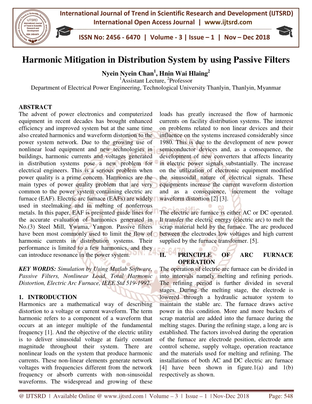
The advent of power electronics and computerized equipment in recent decades has brought enhanced efficiency and improved system but at the same time also created harmonics and waveform distortion to the power system network. Due to the growing use of nonlinear load equipment and new technologies in buildings, harmonic currents and voltages generated in distribution systems pose a new problem for electrical engineers. This is a serious problem when power quality is a prime concern. Harmonics are the main types of power quality problem that are very common to the power system containing electric arc furnace EAF . Electric arc furnace EAFs are widely used in steelmaking and in melting of nonferrous metals. In this paper, EAF is presented guide lines for the accurate evaluation of harmonics generated in No. 3 Steel Mill, Ywama, Yangon. Passive filters have been most commonly used to limit the flow of harmonic currents in distribution systems. Their performance is limited to a few harmonics, and they can introduce resonance in the power system. Nyein Nyein Chan | Hnin Wai Hlaing "Harmonic Mitigation in Distribution System by using Passive Filters" Published in International Journal of Trend in Scientific Research and Development (ijtsrd), ISSN: 2456-6470, Volume-3 | Issue-1 , December 2018, URL: https://www.ijtsrd.com/papers/ijtsrd19027.pdf Paper URL: http://www.ijtsrd.com/engineering/electrical-engineering/19027/harmonic-mitigation-in-distribution-system-by-using-passive-filters/nyein-nyein-chan<br>

E N D
International Journal of Trend in International Open Access Journal International Open Access Journal | www.ijtsrd.com International Journal of Trend in Scientific Research and Development (IJTSRD) Research and Development (IJTSRD) www.ijtsrd.com ISSN No: 2456 ISSN No: 2456 - 6470 | Volume - 3 | Issue – 1 | Nov 1 | Nov – Dec 2018 Harmonic Mitigation in Distribution System n Distribution System by using Passive Filters sing Passive Filters Nyein Nyein Chan Nyein Nyein Chan1, Hnin Wai Hlaing2 1Assistant Lecture, 2Professor Electrical Power Engineering, Technological University Thanlyin, Thanlyin Department of Electrical Power Engineering Thanlyin, Myanmar ABSTRACT The advent of power electronics and computerized equipment in recent decades has brought enhanced efficiency and improved system but at the same time also created harmonics and waveform distortion to the power system network. Due to the growing use of nonlinear load equipment and new technologies in buildings, harmonic currents and voltages generated in distribution systems pose a new problem for electrical engineers. This is a serious problem when power quality is a prime concern. Harmonics are the main types of power quality problem that are very common to the power system containing electric arc furnace (EAF). Electric arc furnace (EAFs) are widely used in steelmaking and in melting of nonferrous metals. In this paper, EAF is presented guide lines for the accurate evaluation of harmonics generated in No.(3) Steel Mill, Ywama, Yangon. Passive filters have been most commonly used to limit the flow of harmonic currents in distribution systems. Their performance is limited to a few harmonics, and they can introduce resonance in the power system. KEY WORDS: Simulation by Using Matlab Software, Passive Filters, Nonlinear Load, Total Harmonic Distortion, Electric Arc Furnace, IEEE Std 519 1.INTRODUCTION Harmonics are a mathematical way of describing distortion to a voltage or current waveform. The term harmonic refers to a component of a waveform that occurs at an integer multiple of the fundamental frequency [1]. And the objective of the electric utility is to deliver sinusoidal voltage at fairly constant magnitude throughout their system. There are nonlinear loads on the system that produce harmonic currents. These non-linear elements generate network voltages with frequencies different from the network frequency or absorb currents with non waveforms. The widespread and growing of these waveforms. The widespread and growing of these loads has greatly increased the flow of harmonic currents on facility distribution systems. The interest on problems related to non linear devices and their influence on the systems increased considerably since 1980. This is due to the development of new power semiconductor devices and, as a consequence, the development of new converters that affects linearity in electric power signals substantially. The increa on the utilization of electronic equipment modified the sinusoidal nature of electrical signals. These equipments increase the current waveform distortion and as a consequence, increment the voltage waveform distortion [2] [3]. The electric arc furnace is either AC or DC operated. It transfer the electric energy (electric arc) to melt the scrap material held by the furnace. The arc produced between the electrodes low voltages and high current supplied by the furnace transformer. [5]. II. PRINCIPLE OF OPERATION The operation of electric arc furnace can be divided in into intervals namely melting and refining periods. The refining period is further divided in several stages. During the melting stage, the electrode is lowered through a hydraulic ac maintain the stable arc. The furnace draws active power in this condition. More and more buckets of scrap material are added into the furnace during the melting stages. During the refining stage, a long arc is established. The factors involved during the operation of the furnace are electrode position, electrode arm control scheme, supply voltage, operation reactance and the materials used for melting and refining. The installations of both AC and DC electric arc furnace [4] have been shown in figure.1(a) and 1(b) respectively as shown. The advent of power electronics and computerized equipment in recent decades has brought enhanced efficiency and improved system but at the same time also created harmonics and waveform distortion to the power system network. Due to the growing use of inear load equipment and new technologies in buildings, harmonic currents and voltages generated in distribution systems pose a new problem for electrical engineers. This is a serious problem when power quality is a prime concern. Harmonics are the pes of power quality problem that are very common to the power system containing electric arc furnace (EAF). Electric arc furnace (EAFs) are widely used in steelmaking and in melting of nonferrous metals. In this paper, EAF is presented guide lines for accurate evaluation of harmonics generated in No.(3) Steel Mill, Ywama, Yangon. Passive filters have been most commonly used to limit the flow of harmonic currents in distribution systems. Their performance is limited to a few harmonics, and they oduce resonance in the power system. loads has greatly increased the flow of harmonic currents on facility distribution systems. The interest on problems related to non linear devices and their nfluence on the systems increased considerably since 1980. This is due to the development of new power semiconductor devices and, as a consequence, the development of new converters that affects linearity in electric power signals substantially. The increase on the utilization of electronic equipment modified the sinusoidal nature of electrical signals. These equipments increase the current waveform distortion and as a consequence, increment the voltage is either AC or DC operated. It transfer the electric energy (electric arc) to melt the scrap material held by the furnace. The arc produced between the electrodes low voltages and high current supplied by the furnace transformer. [5]. PRINCIPLE OF ARC ARC F FURNACE The operation of electric arc furnace can be divided in into intervals namely melting and refining periods. The refining period is further divided in several stages. During the melting stage, the electrode is lowered through a hydraulic actuator system to maintain the stable arc. The furnace draws active power in this condition. More and more buckets of scrap material are added into the furnace during the melting stages. During the refining stage, a long arc is Simulation by Using Matlab Software, Passive Filters, Nonlinear Load, Total Harmonic Distortion, Electric Arc Furnace, IEEE Std 519-1992. Harmonics are a mathematical way of describing distortion to a voltage or current waveform. The term harmonic refers to a component of a waveform that occurs at an integer multiple of the fundamental frequency [1]. And the objective of the electric utility is to deliver sinusoidal voltage at fairly constant magnitude throughout their system. There are nonlinear loads on the system that produce harmonic linear elements generate network voltages with frequencies different from the network frequency or absorb currents with non-sinusoidal lved during the operation of the furnace are electrode position, electrode arm control scheme, supply voltage, operation reactance and the materials used for melting and refining. The installations of both AC and DC electric arc furnace in figure.1(a) and 1(b) @ IJTSRD | Available Online @ www.ijtsrd.com www.ijtsrd.com | Volume – 3 | Issue – 1 | Nov-Dec 2018 Dec 2018 Page: 548
International Journal of Trend in Scientific Research and Development (IJTSRD) ISSN: 2456 International Journal of Trend in Scientific Research and Development (IJTSRD) ISSN: 2456 International Journal of Trend in Scientific Research and Development (IJTSRD) ISSN: 2456-6470 III. VOLTAGE AND CURRENT HARMONIC LIMITS According to IEEE Std 519- distortion on power system 69kV and below is limited to 5.0% total harmonic distorti individual harmonic limited to 3%. The current harmonic limits vary based on the short circuit strength of the system they are being injected into. Essentially, the more system is able to handle harmonic currents, the more the customer i to inject [6]. Table .1 IEEE Std 519-1992 Harmonic Voltage Limits Voltage Distortion Limits Individual Voltage Distortion (%) Below 69kV 3.0 69kV to 161kV 1.5 161kV and above Table .2 IEEE Std 519-1992 Harmonic Current Limits Current Distortion Limits for General Distribution Systems (120V Through 69kV) Maximum Harmonic Current Distortion in Percent of IL Individual Harmonic Order ( Odd Harmonic ) 11- 16 <20 4.0 2.0 20<50 7.0 3.5 50<100 10.0 4.5 100<1000 12.0 5.5 >1000 15.0 7.0 IV. HARMONIC FILTERS Harmonics currents are created by nonlinear loads that generate non-sinusoidal current on distribution power system. Nonlinear devices such as power electronics converters can inject harmonics alternating currents (AC) in the electrical power system. Therefore, the growing use of nonlinear loads in commercial, residential and industrial are becoming more harmonic problems at utilities and customers sides. Harmonics are the most important drawbacks of power quality in the power distribution system. With the increase of nonlinear loads in the power system, more and more harmonic mitigation techniques are required. There are three types of filter required. There are three types of filter VOLTAGE AND CURRENT HARMONIC 1992, harmonic voltage distortion on power system 69kV and below is limited to 5.0% total harmonic distortion (THD) with each individual harmonic limited to 3%. The current harmonic limits vary based on the short circuit strength of the system they are being injected into. Essentially, the more system is able to handle harmonic currents, the more the customer is allowed Figure 1(a) Installation of AC Arc Furnace Figure 1(a) Installation of AC Arc Furnace 1992 Harmonic Voltage Voltage Distortion Limits Figure 1(b) Installation of DC Arc Furnace Figure 1(b) Installation of DC Arc Furnace Individual Voltage Distortion (%) Total Voltage Distortion THDV (%) 5.0 2.5 Bus Voltage at PCC A transformer directly energizes furnace electrodes in a high current circuit in AC arc furnace , whereas DC furnace employ a controlled rectifier to supply dc to the furnace electrodes. Arc furnace operation may be classified into stages, depending on the status of the melt and the time lapse from the initial energizing of the unit. During the melting period, pieces o create momentary short circuits on the secondary side of the furnace transformer. These load changes effect the arc characteristics, causing fluctuations of current. The current fluctuations cause variations in reactive power, which cause a momentary voltage drop or flicker, both at the supply bus and at nearby buses in the interconnected system. The arc currents are more uniform during the refining period and result in less impact on the power quality of the system. Arc furnaces also create harmonic load currents and asynchronous spectral components. represent an important power quality issue, because they may cause undesirable operating conditions. 100MVA 66kV Source A transformer directly energizes furnace electrodes in a high current circuit in AC arc furnace , whereas DC e employ a controlled rectifier to supply dc to the furnace electrodes. Arc furnace operation may be classified into stages, depending on the status of the melt and the time lapse from the initial energizing of the unit. During the melting period, pieces of steel create momentary short circuits on the secondary side of the furnace transformer. These load changes effect the arc characteristics, causing fluctuations of current. The current fluctuations cause variations in reactive 1.0 1.5 1992 Harmonic Current Limits Current Distortion Limits for General Distribution Systems (120V Through 69kV) Maximum Harmonic Current Distortion in Percent of IL Individual Harmonic Order ( Odd Harmonic ) ary voltage drop or flicker, both at the supply bus and at nearby buses in the interconnected system. The arc currents are more uniform during the refining period and result in less impact on the power quality of the system. Arc 17- 22 1.5 2.5 4.0 5.0 17 22 1.5 2.5 4.0 5.0 6.0 6.0 23- 35 0.6 1.0 1.5 2.0 2.5 ISC/IL <11 >35 TDD 0.5 0.5 0.7 1.0 1.4 5.0 8.0 12.0 15.0 20.0 ic load currents and components. asynchronous represent an important power quality issue, because they may cause undesirable operating conditions. spectral Harmonics Harmonics 60MVA 66/33kV TR HARMONIC FILTERS Harmonics currents are created by nonlinear loads sinusoidal current on distribution power system. Nonlinear devices such as power electronics converters can inject harmonics alternating currents (AC) in the electrical power system. fore, the growing use of nonlinear loads in commercial, residential and industrial are becoming more harmonic problems at utilities and customers sides. Harmonics are the most important drawbacks of power quality in the power distribution system. With increase of nonlinear loads in the power system, more and more harmonic mitigation techniques are 33kV Bus bar 33kV Bus bar 15MVA 33/11kV TR 15MVA 15 11kV TR 33/11 11kV Bus bar 11kV Bus bar 12MVA 11/0.42kV TR 8MVA 11/0.2kV TR 5MVA 11/0.4kV TR MVA kV TR 2MVA 11/6.6kV TR 2.5MVA 11/0.4kV EAF Furnace LRF Furnace Wire Bolt Nut Production uction Nut SVC Crusher Motor Production : Index: TR = Transformer Figure.2 Complete Model of No (3) Ywama Steel Mill Figure.2 Complete Model of No (3) Ywama Steel @ IJTSRD | Available Online @ www.ijtsrd.com www.ijtsrd.com | Volume – 3 | Issue – 1 | Nov-Dec 2018 Dec 2018 Page: 549
International Journal of Trend in Scientific Research and Development (IJTSRD) ISSN: 2456 International Journal of Trend in Scientific Research and Development (IJTSRD) ISSN: 2456 International Journal of Trend in Scientific Research and Development (IJTSRD) ISSN: 2456-6470 1.Passive Filters 2.Active Filters 3.Hybrid Filters [8][9]. Passive Filters: Passive filters arrangements of R, L, and C elements connected in different combinations to gain desired suppression of harmonics. They are employed either to shunt the harmonic currents off the line or to block their flow between parts of the system by tuning the elements to create a resonance at a selected frequency. They also provide the reactive power compensation to the system and hence improve the power quality. However, they have the disadvantage of potentially interacting adversely with the power system and the performance of passive filter depends mainly on the system source impedance. On the other hand they can be used for elimination of a particular harmonic frequency, so number of passive filters increase with increase of harmonics on the system. They can be classified into: 1.Passive Shunt Filter 2.Passive Series Filter a.i. Passive Shunt Filter connection. A passive type series passive filter has property of purely inductive type or LC tuned characteristics. The main component of passive series filter in AC line reactor and DC link filter. connection. A passive type series passive filter has property of purely inductive type or LC tuned characteristics. The main component of passive serie filter in AC line reactor and DC link filter. V. SIMULATION MODELS AND RESULTS SIMULATION MODELS AND RESULTS Passive arrangements of R, L, and C elements connected in different combinations to gain desired suppression of harmonics. They are employed either to shunt the harmonic currents off the line or to block their flow en parts of the system by tuning the elements to create a resonance at a selected frequency. They also provide the reactive power compensation to the system and hence improve the power quality. However, they have the disadvantage of potentially g adversely with the power system and the performance of passive filter depends mainly on the system source impedance. On the other hand they can be used for elimination of a particular harmonic frequency, so number of passive filters increase with filters are are basically basically topologies topologies or or Figure .5 Simulation Model of Electric Arc Furnace Figure .5 Simulation Model of Electric Arc Furnace without Filter in No.(3) Ywama Steel Mill without Filter in No.(3) Ywama Steel Mill Figure.6 Total Harmonic Distortion Voltage Waveform without Filter for EAF with Bar (relative Figure.6 Total Harmonic Distortion Voltage Waveform without Filter for EAF wit to fundamental) to fundamental) C C L L Figure .3 Shunt filter connection Figure .3 Shunt filter connection Passive filters are connected in parallel with the system. Figure .3 illustrates the parallel passive filter connection. The shunt may be grounded in one of its terminations, and then it will be passed only for the tuned harmonic current and a part of the fundamental current. The passive shunt type filter is that carry fraction of current so the whole system AC power losses are reduced compare to series type filter. V. ii. Passive Series Filter Passive filters are connected in parallel with the Figure .3 illustrates the parallel passive filter connection. The shunt may be grounded in one of its terminations, and then it will be passed only for the tuned harmonic current and a part of the fundamental current. The passive shunt type filter is that it only carry fraction of current so the whole system AC power losses are reduced compare to series type filter. Figure.7 Total Harmonic Distortion Voltage Waveform without Filter for EAF with List (relative Figure.7 Total Harmonic Distortion Voltage Waveform without Filter for EAF with List (relative to fundamental) to fundamental) ii. Passive Series Filter Figure.8 Total Harmonic Distortion Current Waveform without Filter for EAF with Bar (relative Figure.8 Total Harmonic Distortion Current Waveform without Filter for EAF with Bar (relative to fundamenta to fundamental) Figure .4 Series filter connection Figure .4 Series filter connection Passive filters are connected in series with the system. Figure .4 illustrates the series passive filter Figure .4 illustrates the series passive filter Passive filters are connected in series with the system. @ IJTSRD | Available Online @ www.ijtsrd.com www.ijtsrd.com | Volume – 3 | Issue – 1 | Nov-Dec 2018 Dec 2018 Page: 550
International Journal of Trend in Scientific Research and Development (IJTSRD) ISSN: 2456 International Journal of Trend in Scientific Research and Development (IJTSRD) ISSN: 2456 International Journal of Trend in Scientific Research and Development (IJTSRD) ISSN: 2456-6470 Figure.9 Total Harmonic Distortion Current Waveform without Filter for EAF with List (relative to fundamental) Figure.9 Total Harmonic Distortion Current Waveform without Filter for EAF with List (relative Figure.13 Total Harmonic Distortion Current Waveform with PF for EAF with Bar (relative to fundamental) Figure.13 Total Harmonic Distortion Curre Waveform with PF for EAF with Bar (relative to fundamental) Figure.10 Simulation Model of Electric Arc Furnace with Passive Filter (PF) Figure.10 Simulation Model of Electric Arc Furnace Figure.14 Total Harmonic Distortion Current Waveform with PF for EAF with List (relative to fundamental) Table.3 Comparison of Total Harmonics Voltage & Current Distortion % without and wit System THD Without Filter 24.73% With Passive Filter Figure.14 Total Harmonic Distortion Current Waveform with PF for EAF with List (relative to fundamental) Table.3 Comparison of Total Harmonics Voltage & Current Distortion % without and with PF THDV (%) THDI (%) 24.73% 8.26% 1.52% 2.62% 2.62% VI. The new block developed proved to be effective in harmonic distortion analysis in a steel plants as carried out in this paper. Here the total harmonic distortion (THD) was measured by the THD block in Simulink. The distortion for both voltage and current due to the steel plant were excessive and could be mitigated using passive filter of commensurable design in proposed. According to the simulation results above the figures, the THD and THDI(%) is 8.26% at the point of common coupling (PCC) without using the mitigation techniques in present conditions. The harmonic twenty orders are measured and among them, 11 13th (Ywama, Yangon). After using the passive harmonic filters, the THDV is 2.62% and fundamental value, thus meeting the limit of harmonic standard of IEEE Standard 519 is harmonic mitigation in distribution system by using active and hybrid harmonic filters. CONCLUSION AND FUTURE SCOPE CONCLUSION AND FUTURE SCOPE The new block developed proved to be effective in harmonic distortion analysis in a steel plants as carried out in this paper. Here the total harmonic distortion (THD) was measured by the THD block in Simulink. The distortion for both voltage and current ue to the steel plant were excessive and could be mitigated using passive filter of commensurable design in proposed. According to the simulation results above the figures, the THDV(%) is 24.73% and THDI(%) is 8.26% at the point of common without using the mitigation techniques in present conditions. The harmonic twenty orders are measured and among them, 11st and orders are dominant in No.(3) Steel Mill (Ywama, Yangon). After using the passive harmonic is 2.62% and THDI is 1.52% of the fundamental value, thus meeting the limit of harmonic standard of IEEE Standard 519-1992. The future work is harmonic mitigation in distribution system by using active and hybrid harmonic filters. Figure.11 Total Harmonic Distortion Voltage Waveform with PF for EAF with Bar (relative to fundamental) Figure.11 Total Harmonic Distortion Voltage Waveform with PF for EAF with Bar (relative to Figure.12 Total Harmonic Distortion Voltage Waveform with PF for EAF with List (relative to fundamental) Figure.12 Total Harmonic Distortion Voltage Waveform with PF for EAF with List (relative to orders are dominant in No.(3) Steel Mill @ IJTSRD | Available Online @ www.ijtsrd.com www.ijtsrd.com | Volume – 3 | Issue – 1 | Nov-Dec 2018 Dec 2018 Page: 551
International Journal of Trend in Scientific Research and Development (IJTSRD) ISSN: 2456 International Journal of Trend in Scientific Research and Development (IJTSRD) ISSN: 2456 International Journal of Trend in Scientific Research and Development (IJTSRD) ISSN: 2456-6470 4.Reuben F. Burch IV, Senior Member, IEEE “Thoughts on Improving the Electric Arc Furnace Model”. 5.Amarjeet Singh, Ravindra Kumar Singh, Asheesh Kumar Singh “Power Quality Issue of Electric Arc Furnace and their Mitigations ISSN: 2349-6495(p) 2456 4, Apr-2017. 6.Thomas M. Blooming, P.E, Daniel J. Carnovale P.E. “Application of IEEE Std 519 Harmonic Limits”. 7.Rooh UI Amin Shaikh, Abdul Basit Lashari, Irfan Ansari, “Harmonic Analysis and Mitigation U Passive Filters” January, 2015. 8.Rustemli, S. and Cengiz, M.S. 2016, “Passive Filter Solution and Simulation Perfornance in Industrial Plants”. Bitlis Eren University J Science and Technology, Turkey. 9.Nassif, A.B., Xu, W. and Freitas Investigation on the Selection of Filter Topologes for Passive Filter Applications”. IEEE PES General Meeting, 2009. ACKNOWLEDGMENTS I greatly appreciate to all teachers from the Department of Electrical Technological University (Thanlyin) who work in Research. I would like to give great thanks to Research Department of Electrical Technological University permission to study related on-going research projects. REFERENCES 1.Ashok, S. “Harmonic in distribution system of an educational institution” IEEE transactions on power quality 98 pages 145-150, 1998. 2.Alejandro O.M. and Gustavo A.R. “Instantaneous p-q theory for harmonic compensation via shunt active power filter” IEEE transactions on power electronics and power quality applications, page 1-4, 2013. 3.Jamil M. “Harmonics in Adjustable Speed Drives” IEEE transactions on information and emerging technologies, page 1-6, 2007. Reuben F. Burch IV, Senior Member, IEEE “Thoughts on Improving the Electric Arc Furnace to all teachers from the Electrical Department Technological University (Thanlyin) who work in of Power Power Engineering, Engineering, Amarjeet Singh, Ravindra Kumar Singh, Asheesh Kumar Singh “Power Quality Issue of Electric Arc Furnace and their Mitigations – A Review”, 6495(p) 2456-1908(O), Vol-4, Issue- I would like to give great thanks to Research Department of Electrical Technological University Power (Thanlyin) (Thanlyin) Power Engineering, f for going research Engineering, kind Thomas M. Blooming, P.E, Daniel J. Carnovale P.E. “Application of IEEE Std 519-1992 Rooh UI Amin Shaikh, Abdul Basit Lashari, Irfan Ansari, “Harmonic Analysis and Mitigation Using Passive Filters” January, 2015. Ashok, S. “Harmonic in distribution system of an educational institution” IEEE transactions on 150, 1998. Rustemli, S. and Cengiz, M.S. 2016, “Passive Filter Solution and Simulation Perfornance in Industrial Plants”. Bitlis Eren University J Science Alejandro O.M. and Gustavo A.R. “Instantaneous q theory for harmonic compensation via shunt active power filter” IEEE transactions on power electronics and power quality applications, page Nassif, A.B., Xu, W. and Freitas, W.2009, “An Investigation on the Selection of Filter Topologes for Passive Filter Applications”. IEEE PES Jamil M. “Harmonics in Adjustable Speed Drives” IEEE transactions on information and emerging @ IJTSRD | Available Online @ www.ijtsrd.com www.ijtsrd.com | Volume – 3 | Issue – 1 | Nov-Dec 2018 Dec 2018 Page: 552