Download
1 / 4
40 likes | 41 Views
This paper focuses on the effective switching system that allows user control of electrical appliances using smart phone. This system will be able to ease the effort of physically challenged individuals in controlling home and office appliances. To operate the effective switching system, the user should send DTMF Dual Tone Multi Frequency to system phone via Global System for Mobile Communication GSM . In the system unit, DTMF decoder decodes the signals from the system phone. These decoded signals are fed to the PIC16F677 microcontroller to perform the required function. Thae Hsu Thoung | Zin Ma Ma Myo "Implementation of Effective Switching System for Controlling Home and Office Appliances" Published in International Journal of Trend in Scientific Research and Development (ijtsrd), ISSN: 2456-6470, Volume-3 | Issue-5 , August 2019, URL: https://www.ijtsrd.com/papers/ijtsrd26610.pdf Paper URL: https://www.ijtsrd.com/engineering/electronics-and-communication-engineering/26610/implementation-of-effective-switching-system-for-controlling-home-and-office-appliances/thae-hsu-thoung<br>

E N D
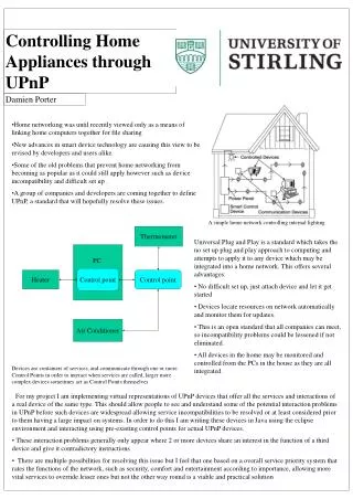
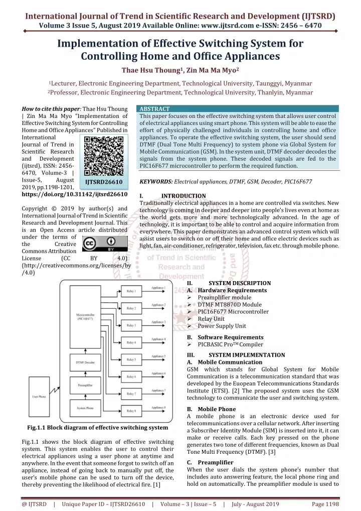
International Journal of Trend in Scientific Research and Development (IJTSRD) Volume 3 Issue 5, August 2019 Available Online: www.ijtsrd.com e-ISSN: 2456 – 6470 Implementation of Effective Switching System for Controlling Home and Office Appliances Thae Hsu Thoung1, Zin Ma Ma Myo2 1Lecturer, Electronic Engineering Department, Technological University, Taunggyi, Myanmar 2Professor, Electronic Engineering Department, Technological University, Thanlyin, Myanmar How to cite this paper: Thae Hsu Thoung | Zin Ma Ma Myo "Implementation of Effective Switching System for Controlling Home and Office Appliances" Published in International Journal of Trend in Scientific Research and Development (ijtsrd), ISSN: 2456- 6470, Volume-3 | Issue-5, August 2019, pp.1198-1201, https://doi.org/10.31142/ijtsrd26610 Copyright © 2019 by author(s) and International Journal of Trend in Scientific Research and Development Journal. This is an Open Access article distributed under the terms of the Creative Commons Attribution License (CC (http://creativecommons.org/licenses/by /4.0) ABSTRACT This paper focuses on the effective switching system that allows user control of electrical appliances using smart phone. This system will be able to ease the effort of physically challenged individuals in controlling home and office appliances. To operate the effective switching system, the user should send DTMF (Dual Tone Multi Frequency) to system phone via Global System for Mobile Communication (GSM). In the system unit, DTMF decoder decodes the signals from the system phone. These decoded signals are fed to the PIC16F677 microcontroller to perform the required function. KEYWORDS: Electrical appliances, DTMF, GSM, Decoder, PIC16F677 I. INTRODUCTION Traditionally electrical appliances in a home are controlled via switches. New technology is coming in deeper and deeper into people’s lives even at home as the world gets more and more technologically advanced. In the age of technology, it is important to be able to control and acquire information from everywhere. This paper demonstrates an advanced control system which will assist users to switch on or off their home and office electric devices such as light, fan, air-conditioner, refrigerator, television, fax etc. through mobile phone. IJTSRD26610 BY 4.0) II. A.Hardware Requirements Preamplifier module DTMF MT8870D Module PIC16F677 Microcontroller Relay Unit Power Supply Unit B.Software Requirements PICBASIC ProTM Compiler III. SYSTEM IMPLEMENTATION A.Mobile Communication GSM which stands for Global System for Mobile Communication is a telecommunication standard that was developed by the Euopean Telecommunications Standards Institute (ETSI). [2] The proposed system uses the GSM technology to communicate the user and switching system. B.Mobile Phone A mobile phone is an electronic device used for telecommunications over a cellular network. After inserting a Subscriber Identity Module (SIM) is inserted into it, it can make or receive calls. Each key pressed on the phone generates two tone of different frequencies, known as Dual Tone Multi Frequency (DTMF). [3] C.Preamplifier When the user dials the system phone’s number that includes auto answering feature, the local phone ring and hold on automatically. The preamplifier module is used to SYSTEM DESCRIPTION Fig.1.1 Block diagram of effective switching system Fig.1.1 shows the block diagram of effective switching system. This system enables the user to control their electrical appliances using a user phone at anytime and anywhere. In the event that someone forgot to switch off an appliance, instead of going back to manually put off, the user’s mobile phone can be used to turn off the device, thereby preventing the likelihood of electrical fire. [1] @ IJTSRD | Unique Paper ID – IJTSRD26610 | Volume – 3 | Issue – 5 | July - August 2019 Page 1198
International Journal of Trend in Scientific Research and Development (IJTSRD) @ www.ijtsrd.com eISSN: 2456-6470 boost the signal from system phone sufficiently. Fig.3.1 shows the K1803 preamplifier module. [4] requirements. Features of the device as seen in data sheet are as follows: [6] Precision Internal Oscillator Power-Saving Sleep mode Wide Operating Voltage Range (2.0V-5.5V) Industrial and Extended Temperature Range Power-on Reset (POR) Power-up Timer (PWRTE) and Oscillator Start-up Timer (OST) Brown-out Reset (BOR) with Software Control Option Enhanced Low-Current Watchdog Timer (WDT) with On-Chip Oscillator (Software selectable nominal 268 Seconds with Full Prescaler) with Software Enable Multiplexed Master Clear/Input pin Programmable Code Protection High Endurance Flash/EEPROM Cell (100,000 write Flash endurance, 1,000,000 write EEPROM endurance, Flash/Data EEPROM retention: > 40 years) Enhanced USART Module (Supports RS-485, RS-232 and LIN 2.0, Auto-Baud Detect, Auto-wake-up on Start bit) F.Relay Unit Relays are switches that open and close circuits electromechanically or electronically. In this system BC547 (8 no.) transistors are used as relay driver. A small current at its base controls a larger current at collector and emitter terminals. [7] Fig.3.1 Preamplifier module (K1803) [4] D.Decoder Module (DTMF MT8870D) The MT8870D/MT8870D-1 is a complete DTMF receiver integrating both the band split filter and digital decoder functions. The filter section uses switched capacitor techniques for high and low group filters; the decoder uses digital counting techniques to detect and decode all 16 DTMF tone-pairs into a 4-bit code. [5] The DTMF keypad is shown in Fig.3.2. Fig.3.2 DTMF keypad Fig.3.4 Relay driver (BC547) [7] The module MT8870D detects the dial tone from a telephone line and decodes into 4-bit code. This module is shown in Fig.3.3. Fig.3.3 DTMF MT8870D module [5] E.Microcontroller (PIC16F677) PIC16F677 microcontroller was used for controlling home and office appliances. The PIC16F677 is the 20-pin flash- based, 8-bit CMOS microcontroller with nanoWatt technology. It is easy to program because it has only 35 single word instructions. This model is common in many applications and its features are sufficient for system Fig.3.5 Photo of Relay circuit G.Power Supply Unit The regulated power supply is used to supply the required voltages needed by the each part of overall system. The preamplifier, DTMF decoder and microcontroller units are supplied with a fairly stable 5V. To operate the relay, stable 12V is supplied. @ IJTSRD | Unique Paper ID – IJTSRD26610 | Volume – 3 | Issue – 5 | July - August 2019 Page 1199
International Journal of Trend in Scientific Research and Development (IJTSRD) @ www.ijtsrd.com eISSN: 2456-6470 The GSM technology was used for receiving Dual Tone Multi Frequency (DTMF) from user's mobile phone. This frequency was received by system phone that already has auto answer system. The system phone automatically enable the controller to take any further action such as to control the home or office appliances. V. EXPERIMENTAL RESULTS If microcontroller receives the password of two digits: “ON” digit (25) and device digit (11), the corresponding appliance 1 will be switched on via relay circuit. The appliance 1 will be switched off whether the password two digits: “OFF” digit (25) and device digit (21) was received. Fig.3.6 Power supply circuit for input preamplifier Fig.3.7 Power supply circuit for output relay circuit Fig.5.1. Working condition of appliance 1 If microcontroller receives the password of two digits: “ON” digit (25) and device digit (12), the corresponding appliance 1 will be switched on via relay circuit. The appliance 1 will be switched off whether the password two digits: “OFF” digit (25) and device digit (22) was received. Fig.3.8 Photo of power supply circuit SYSTEM FLOWCHART IV. Fig.5.2. Working condition of appliance 2 If microcontroller receives the password of two digits: “ON” digit (25) and device digit (13), the corresponding appliance 1 will be switched on via relay circuit. The appliance 1 will be switched off whether the password two digits: “OFF” digit (25) and device digit (23) was received. Fig.5.3. Working condition of appliance 3 If microcontroller receives the password of two digits: “ON” digit (25) and device digit (14), the corresponding appliance 1 will be switched on via relay circuit. The appliance 1 will be switched off whether the password two digits: “OFF” digit (25) and device digit (24) was received. Fig.4.1 Flowchart of effective switching system @ IJTSRD | Unique Paper ID – IJTSRD26610 | Volume – 3 | Issue – 5 | July - August 2019 Page 1200
International Journal of Trend in Scientific Research and Development (IJTSRD) @ www.ijtsrd.com eISSN: 2456-6470 Fig.5.4. Working condition of appliance 4 Fig.5.8 working condition of appliance 8 CONCLUSIONS The effective switching system for controlling home and office appliances was designed and constructed. The system was integrated with microcontroller (PIC 16F677) and GSM network interface using PIC basic pro programming language. The system is activated when user sends the DTMF decoder to system phone at home or office. Upon receiving the DTMF command, user can be written four digits password using user phone. After system phone received that password, it starts to control the electrical appliances. This saves energy and time used in switching on or off manually since the appliances can be controlled from this remote system. ACKNOWLEDDMENT The author wishes to express her deep gratitude to Dr. Zin Ma Ma Myo, Professor and Head, Department of Electronic Engineering, Technological University (Thanlyin), for her permission and the support. The author is also indebted to all of her teachers in the Department of Electronic Engineering, who contributed their knowledge and support during the study and research periods. A special note of thank is also intended to Dr. Thet Mon Aye, Lecturer, Department of Electrical Power Engineering, West Yangon Technological University, who helped her with necessary assistance for her research. REFERENCES [1]A. P. Bagade, S. L. Haridas and P. R. Indurkar, (2012), “Development of a mobile Based Device Remote Control with Voice Acknowledgement,” in National Conference on Innovative Paradigms in Engineering & Technology (NCIPET-2012) [2]A. C. Ohajianya, O. E. Abumere, E. Osarolube and V. C. Ihesineke, (2014), “Implementation of GSM Remote Switching Using Locally Available Components in Nigeria,” International Journal of Engineering and Science (IJES), vol. 3, no. 7, pp. 13-23 [3]C. K. Das, M. Sanaullah, M. G. Sarower and M. M. Hassan, (2009) “Development of a Cell Phone Based Remote Control System: An Effective Switching System for Controlling Home and Office Appliances,” International Journal of Electrical & Computer Sciences (IJECS- IJENS), vol. 9, no. 10, pp. 23-29 [4]https://www.velleman.eu/downloads/0/illustrated/ill ustrated_assembly_manual_k1803_rev.pdf [5]https://www.microsemi.com/document-portal/ doc_download/ 127041-mt8870d-datasheet-oct2006 [6]Microchip Technology PIC16F631/677/685/687/689/690 Data Sheet [7]https://www.theengineeringprojects.com/2017/06/in troduction-to-bc547.html If microcontroller receives the password of two digits: “ON” digit (25) and device digit (15), the corresponding appliance 1 will be switched on via relay circuit. The appliance 1 will be switched off whether the password two digits: “OFF” digit (25) and device digit (25) was received. VI. Fig.5.5. Working condition of appliance 5 If microcontroller receives the password of two digits: “ON” digit (25) and device digit (16), the corresponding appliance 1 will be switched on via relay circuit. The appliance 1 will be switched off whether the password two digits: “OFF” digit (25) and device digit (26) was received. Fig.5.6. Working condition of appliance 6 If microcontroller receives the password of two digits: “ON” digit (25) and device digit (17), the corresponding appliance 1 will be switched on via relay circuit. The appliance 1 will be switched off whether the password two digits: “OFF” digit (25) and device digit (27) was received. Fig.5.7 working condition of appliance 7 If microcontroller receives the password of two digits: “ON” digit (25) and device digit (18), the corresponding appliance 1 will be switched on via relay circuit. The appliance 1 will be switched off whether the password two digits: “OFF” digit (25) and device digit (28) was received. Inc (2008), @ IJTSRD | Unique Paper ID – IJTSRD26610 | Volume – 3 | Issue – 5 | July - August 2019 Page 1201