Download
1 / 9
90 likes | 94 Views
Biodiesel Ethanol Diesel blends are believed to be able to improve the combustion characteristics since biodiesel, ethanol, and diesel have different fuel characteristics. A model was developed using GT POWER, an engine cycle simulation for a biodiesel ethanol diesel BED fueled direct injection compression ignition engine corresponding to a 4.5 liter, TecQuipment TD115 MK II single cylinder diesel engine was used. At selected operating conditions, Intport 1 and Intvalve 1combustion parameters of the engine at constant load of 1000 g at various speeds of 1760 rpm, 1840 rpm, 1920 rpm, 2000 rpm and 2080 rpm were investigated. Results of the static pressure in Intport 1 for BED30 were compared with those obtained with the diesel and found to have the same trends for all the speed conditions, there was a significant pressure drop to less than 2.40 bar within the compression region and rises up above 2.40 bar before the power stroke region. The power and exhaust regions maintained the same trends of pressure fluctuations for both the diesel and BED30. Results of mass flow rate for the same Intport 1 show a steady increase of the maximum mass flow rate with speed, showing the lowest value of 0.18 kg s for BED30 and 0.17 kg s for diesel at 1760 rpm. The results of the average sub volume velocity centroid and diesel in Intport 1 for all speeds followed the same trend with the mass flow rate, but with smoother path at power and exhaust strokes. At the intake region the movement of the charges rise up for all the speed conditions, and reached a peak value of 56.8 m s at 1760 rpm, 59.1 m s at 1840 rpm, 62.7 m s at 1920 rpm, 64.0 m s at 2000 rpm and 71.1 m s at 2080 rpm. The Mass flow rate at the intvalve 1 results showed that at all the speed conditions, the maximum value of lift was at 2600 BDC. Simulated pressure diagram and heat release curves for all speed conditions obtained with BED30 showed good agreement with the results obtained with diesel. I. Yahuza | H. Dandakouta | M. H. Ibrahim | D. Y. Dasin "Modelling and Simulation of Some Combustion Parameters (Intport-1 and Intvalve-1) using Gt-Power Engine Simulation Software with Biodiesel-Ethanol-Diesel Blends as Fuel" Published in International Journal of Trend in Scientific Research and Development (ijtsrd), ISSN: 2456-6470, Volume-3 | Issue-1 , December 2018, URL: https://www.ijtsrd.com/papers/ijtsrd19188.pdf Paper URL: http://www.ijtsrd.com/engineering/automotive-engineering/19188/modelling-and-simulation-of-some-combustion-parameters-intport-1-and-intvalve-1-using-gt-power-engine-simulation-software-with-biodiesel-ethanol-diesel-blends-as-fuel/i-yahuza<br>

E N D
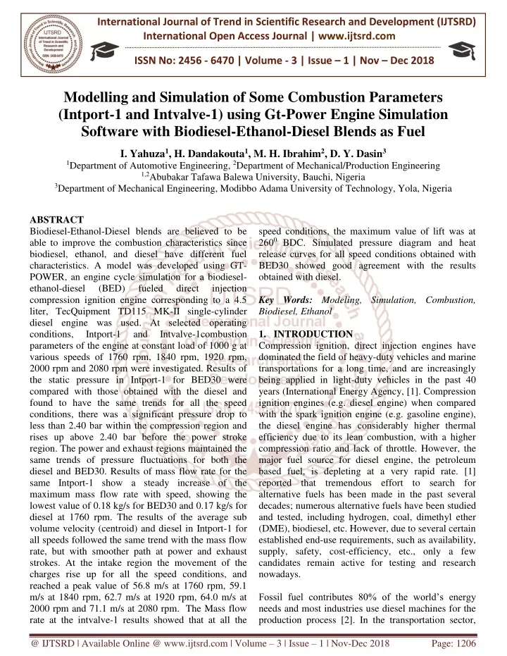
International Journal of Trend in Scientific Research and Development (IJTSRD) International Open Access Journal | www.ijtsrd.com ISSN No: 2456 - 6470 | Volume - 3 | Issue – 1 | Nov – Dec 2018 Modelling and Simulation of Some Combustion Parameters (Intport-1 and Intvalve-1) using Gt-Power Engine Simulation Software with Biodiesel-Ethanol-Diesel Blends as Fuel I. Yahuza1, H. Dandakouta1, M. H. Ibrahim2, D. Y. Dasin3 1Department of Automotive Engineering, 2Department of Mechanical/Production Engineering 1,2Abubakar Tafawa Balewa University, Bauchi, Nigeria 3Department of Mechanical Engineering, Modibbo Adama University of Technology, Yola, Nigeria ABSTRACT Biodiesel-Ethanol-Diesel blends are believed to be able to improve the combustion characteristics since biodiesel, ethanol, and diesel have different fuel characteristics. A model was developed using GT- POWER, an engine cycle simulation for a biodiesel- ethanol-diesel (BED) fueled compression ignition engine corresponding to a 4.5 liter, TecQuipment TD115 MK-II single-cylinder diesel engine was used. At selected operating conditions, Intport-1 and parameters of the engine at constant load of 1000 g at various speeds of 1760 rpm, 1840 rpm, 1920 rpm, 2000 rpm and 2080 rpm were investigated. Results of the static pressure in Intport-1 for BED30 were compared with those obtained with the diesel and found to have the same trends for all the speed conditions, there was a significant pressure drop to less than 2.40 bar within the compression region and rises up above 2.40 bar before the power stroke region. The power and exhaust regions maintained the same trends of pressure fluctuations for both the diesel and BED30. Results of mass flow rate for the same Intport-1 show a steady increase of the maximum mass flow rate with speed, showing the lowest value of 0.18 kg/s for BED30 and 0.17 kg/s for diesel at 1760 rpm. The results of the average sub volume velocity (centroid) and diesel in Intport-1 for all speeds followed the same trend with the mass flow rate, but with smoother path at power and exhaust strokes. At the intake region the movement of the charges rise up for all the speed conditions, and reached a peak value of 56.8 m/s at 1760 rpm, 59.1 m/s at 1840 rpm, 62.7 m/s at 1920 rpm, 64.0 m/s at 2000 rpm and 71.1 m/s at 2080 rpm. The Mass flow rate at the intvalve-1 results showed that at all the speed conditions, the maximum value of lift was at 2600 BDC. Simulated pressure diagram and heat release curves for all speed conditions obtained with BED30 showed good agreement with the results obtained with diesel. Key Words: Modeling, Simulation, Combustion, Biodiesel, Ethanol 1.INTRODUCTION Compression ignition, direct injection engines have dominated the field of heavy-duty vehicles and marine transportations for a long time, and are increasingly being applied in light-duty vehicles in the past 40 years (International Energy Agency, [1]. Compression ignition engines (e.g. diesel engine) when compared with the spark ignition engine (e.g. gasoline engine), the diesel engine has considerably higher thermal efficiency due to its lean combustion, with a higher compression ratio and lack of throttle. However, the major fuel source for diesel engine, the petroleum based fuel, is depleting at a very rapid rate. [1] reported that tremendous effort to search for alternative fuels has been made in the past several decades; numerous alternative fuels have been studied and tested, including hydrogen, coal, dimethyl ether (DME), biodiesel, etc. However, due to several certain established end-use requirements, such as availability, supply, safety, cost-efficiency, etc., only a few candidates remain active for testing and research nowadays. Fossil fuel contributes 80% of the world’s energy needs and most industries use diesel machines for the production process [2]. In the transportation sector, direct injection Intvalve-1combustion @ IJTSRD | Available Online @ www.ijtsrd.com | Volume – 3 | Issue – 1 | Nov-Dec 2018 Page: 1206
International Journal of Trend in Scientific Research and Development (IJTSRD) ISSN: 2456-6470 private vehicles, buses, trucks, and ships also consume significant amounts of diesel and gasoline. This situation leads to a strong dependence of everyday life on fossil fuels. However, the growth of the population is not covered by domestic crude oil production [3]. The emission produced by the combustion of fossil fuels also contributes to the air pollution and global warming [4, 5]. Hence, renewable and clean alternative fuels have received increasing attention for current and future utilization. [6] Reported that biodiesel as one of the promising alternatives to fossil fuel for diesel engines, has become increasingly important due to environmental consequences of using petroleum fuels in diesel engines and the decreasing petroleum resources. Biodiesel can be produced by chemically combining any natural oil or fat with an alcohol such as methanol or ethanol. Methanol has been the most commonly used alcohol in the commercial production of biodiesel [7]. Lots of researches on biodiesel have shown that the fuel made from vegetable oil can be used properly in diesel engines. [8] found that the energy density of biodiesel is quite close to that of regular diesel. Moreover, the use of ethanol blended with diesel was a subject of research in the 1980s and it was shown that ethanol–diesel blends were technically acceptable for the existing diesel engines. The relatively high cost of ethanol production at that time meant that the fuel could only be considered in cases of fuel shortages. Recently, the economics have become much more favourable in the production of ethanol and it is able to compete with standard diesel. Consequently, there has been renewed interest in the ethanol–diesel blends with particular emphasis on emissions reductions. An additional factor that makes ethanol attractive as a fuel substitute is that it is a renewable resource. In modern engine research and study, using hardware experiments alone would be very expensive and time- consuming, and many cause and effect relationships implicit in the test results are often hard to interpret. On the other hand, modelling and simulation approaches, although less precise in predicting the outcome of a specific test, could effectively isolate one variable at a time and conduct parametric studies on it. Therefore, simulation could point out cause- effect relationships more clearly, and a validated model could be a very useful tool to study new type of engines or engines running with new type of fuels. Since people still don’t have a very clear understanding on the effect of using biodiesel- ethanol-diesel blends on a diesel engine, through experimental study, a simulation study of the blends is necessary. GT-POWER is the market leading engine simulation software, used by every major engine manufacturer for the design and development of their engines. It is a part of GT-SUITE, software of Gamma Technologies. GT-POWER counts on two main powerful tools called GT-ISE (Integrated Simulation Environment) that builds, executes, and manages the simulation process; and GT-POST, a post-processing tool that provides access to all the plot data generated by the simulation (GT-Power, 2013). 2.MATERIALS AND METHODS 2.1 Materials Ethanol The chemical formula for ethanol is C2H5OH, sometimes written EtOH or C2H6O. It is also known under the names ethyl alcohol or hydroxyethane and is the type of alcohol found in alcoholic beverages. Ethanol is a rather simple organic molecule consisting of a group of carbon and hydrogen atoms, with a hydroxyl group (oxygen and a hydrogen atom) attached. The ethanol molecule is small and light, having a molecular weight of 46 g/mol [9]. The ethanol used in the research was produced from sawdust of Masonia (Masonia Altissama) wood using simultaneous saccharification and fermentation (SSF) processes. Biodiesel Biodiesel is a clean burning alternative fuel produced from domestic, renewable resources such as plant oils, animal fats, used cooking oil and even from algae [10]. Biodiesel contains no petroleum, but can be blended at any level with petroleum diesel to create a biodiesel blend [11]. Biodiesel blends can be used in compression ignition engines with little or no modifications [12]. The biodiesel used was produced from neem oil, which was extracted from neem seeds (Azadirachta indica) by transesterification method. Diesel fuel Diesel fuel in general is any liquid fuel used in diesel engines, whose fuel ignition takes place without any spark as a result of compression of the inlet air mixture and then injection of fuel [13]. The average chemical formula for common diesel fuel is C12H23, @ IJTSRD | Available Online @ www.ijtsrd.com | Volume – 3 | Issue – 1 | Nov-Dec 2018 Page: 1207
International Journal of Trend in Scientific Research and Development (IJTSRD) ISSN: 2456-6470 ranging approximately from C10H20 to C15H28. The diesel fuel used for this research was purchased at AYM Shafa filling station along Abubakar Tafawa Balewa Road, near Yelwa Bauchi, Nigeria. GT-POWER Engine Simulation Software GT-POWER is the industry standard engine performance simulation, used by all major engine manufacturers and vehicle operators. GT-POWER is used to predict engine performance quantities such as power, torque, airflow, volumetric efficiency, fuel consumption, turbocharger matching, and pumping losses, to name just a few. Beyond basic performance predictions, GT-POWER includes physical models for extending the predictions to include cylinder and tailpipe-out emissions, intake and exhaust system acoustic characteristics (level and quality), in-cylinder and pipe/manifold structure temperature, measured cylinder pressure analysis, and control system modelling. Standard GT-POWER engine models are easily timecapable models for software in the loop (SiL) or hardware in the loop (HiL) simulations. These models may also be included in a full system level simulation within GT-SUITE to provide accurate and physically based engine boundary conditions to the rest of the vehicle [14]. In this research work, the GTise Huge v7.4.0 version (one of the suites in GT-POWER package) was used, whichincludes various solutions for modelling combustion and emissions. 2.2 Methods Blending of the samples The biodiesel, the ethanol and the diesel were blended in dry flask equipped with a magnetic stirrer. The biodiesel-ethanol-diesel blends were produced with (%, v/v) 5, 10, 15, 20, 25, 30 and 35% ethanol with 85, 80, 75, 70, 65, 60 and 55% diesel, and biodiesel was kept at 10% throughout. Thus, the blends were labelled as BED5, BED10, BED15, BED20, BED25, BED30 and BED35, respectively. Modelling and simulation of engine combustion analyses The 1D numerical analyses of GTise Huge package was used to model and simulate the single cylinder diesel engine. Using the modelling tool of GT- POWER, engine cycle simulation for biodiesel- ethanol-diesel fuels and the engine specifications for the test rig, a compression ignition engine was modeled into the GT-POWER software to reflect the single cylinder diesel engine. The data which were obtained from the tests of the physico-chemical properties and engine performance as reported by [15] were used to validate the model and obtain the combustion analyses results. GT-ISE was opened on the PC, the following path was followed: Start → Programs → GTI Applications Group → GTise Huge v7.4.0, from the “Run” menu in GT-POWER, the “Case Setup” was entered; the engine speed of 1760 rpm value was set as Case 1 in the model. Same path was followed to create other cases with 1840 rpm, 1920 rpm, 2000 rpm and 2080 rpm, hence to accomplish this, the “Append Case”, was clicked on. The parameter “CASE” was clicked on, and in the description of Case 1, Case 2, Case 3, Case 4 and Case 5, the speed values “1760 rpm” “1840 rpm”, “1920 rpm”, “2000 rpm” and “2080 rpm” respectively were typed and the “OK” button was clicked. The blue icon was clicked to “Run the Simulation” Pre- processor, when there were “no errors” the yellow icon was clicked to run the Simulation. The model has run successfully, from the Run menu “Open GT- POST” was selected and the results were viewed with GT-POST. Model for combustion analyses in GT-POWER The modelling format in GT-ISE which uses an object-oriented structure was used to develop the engine model for the combustion analyses. The structure is comprised of a three-level hierarchy, viz: Templates, Objects and Parts. Templates are provided which contain the unfilled attributes needed by the model within the program. The templates are made into objects, and when components and connection objects are placed on the project map they become parts and inherit their values from their parent objects. Eleven templates were developed for the purpose of developing the single cylinder compression engine. The templates are: inlet environment, intake runner, intake port, intake and exhaust valves, cylinder, fuel injector, exhaust port and runner, outlet environment and engine crank train. After creating all the templates listed above, the parts were placed on the project map and components were connected together as shown in Plate I. Each object that is seen on the map is now an individual part. GT- performance and toreal- converted @ IJTSRD | Available Online @ www.ijtsrd.com | Volume – 3 | Issue – 1 | Nov-Dec 2018 Page: 1208
International Journal of Trend in Scientific Research and Development (IJTSRD) ISSN: 2456-6470 ISE automatically assigns a name to each part as it is placed on the map. Plate I: Engine model from GT-power software Running the simulation of the model in GT- POWER Since the model was fully built, the case specific input, type of simulation and the desired output were described in the settings menu of the GT-ISE. The model was run using the Run Simulation button on the GT-ISE toolbar and the model was automatically saved for future used. Plate II shows the sample of the simulation window and Plate III presents the results of the simulation. The results were viewed and extracted using the Open GT-POST button on the GT-ISE toolbar and the filename of the .gdx file with the same file name as the model was selected so that the GT- POST post processing program was launched automatically in a new window. The available plots in the cylinder for combustion analyses were illustrated in Plate IV. Plate II: Completed output of the simulation window @ IJTSRD | Available Online @ www.ijtsrd.com | Volume – 3 | Issue – 1 | Nov-Dec 2018 Page: 1209
International Journal of Trend in Scientific Research and Development (IJTSRD) ISSN: 2456-6470 Plate III: Results of the simulated model Plate IV: Available plots for combustion analyses 3.RESULTS AND DISCUSSIONS The results of the combustion analyses were generated after running the simulation of the single cylinder diesel engine model was fuelled with BED30. The parameters were generated from the four sections of the engine model. 3.1 Intport-1 Pressure (static) The static pressures at the intport-1 for diesel and BED30 were generated and presented in Figures 1 and 2 respectively. The results of the static pressure for BED30 were compared with those obtained with the diesel and found to have the same trends for all the speed conditions. For all the cases, the pressure drops to less than 2.40 bar within the compression region and rises up above 2.40 bar before the power stroke BED30 Combustion in GT-POWER [15], reported the performance evaluation results and exhaust emission characterization of BED30 as the best among the remaining blends when compared with diesel. Hence, BED30 was used for combustion analyses in the GT-POWER. Parameters for combustion analyses were generated from four (4) sections in the model, which include: intport-1, intvalve-1, cylinder-1 and exhvalve-1. Only intport-1 and intvalve -1 was considered for this article. In the intport-1, three (3) parameters were investigated that include pressure (static), mass flow rate (at the boundary) and average sub-volume velocity (centroid). At the intvalve-1, two (2) parameters were investigated which include mass flow rate and valve lift. @ IJTSRD | Available Online @ www.ijtsrd.com | Volume – 3 | Issue – 1 | Nov-Dec 2018 Page: 1210
International Journal of Trend in Scientific Research and Development (IJTSRD) ISSN: 2456-6470 Mass flow rate (at the boundary) Figure 3 shows the variations of the mass flow rate with the crank angle at the speeds of 1760 rpm, 1840 rpm, 1920 rpm, 2000 rpm and 2080 rpm for BED30, while Figure 4 shows variations of mass flow rate with crank angle for diesel. For the BED30, the results showed that the mass flow rate from -1800 BDC to the nearly middle of the compression region is negative, and maintains zero value all through the power and exhaust strokes. The same trends were noticed for diesel and it is evident that the intake valve is closed during these processes. For both BED30 and diesel, intake valve opens at 3600 TDC to allow fuel to flow into the combustion chamber with the maximum value of 0.211 kg/s at the speed of 2080 rpm. On the other hand, for diesel the intake valve closes at 537.90 TDC while for BED30 it closes at 539.40 TDC at the speed of 2080 rpm. The results show a steady increase of the maximum mass flow rate with speed, showing the lowest value of 0.18 kg/s for BED30 and 0.17 kg/s for diesel at 1760 rpm. This verifies the hypothesis of Tat et al. (2013) that a mass flow rate at the boundary, to support proper combustion in CI engines, should have the values between 0.17 kg/s to 0.222 kg/s (0.17 kg/s • m 0.222 kg/s). The mass flow rates are below zero starting from -1800 BDC up to the middle of the compression region and maintained 0.00 kg/s throughout the power and exhaust regions for the speed conditions. This agrees with results presented for the pressure against crank angle (Figures 1 and 2). After the exhaust region (3600 TDC), the mass flow rates for all the speed conditions rise to its peak values at the intake region to allow more flow of fuel into the combustion chamber (0.175 kg/s at 1760 rpm, 0.180 kg/s at 1840 rpm, 0.195 kg/s at 1920 rpm, 0.212 kg/s at 2000 rpm and 0.220 kg/s at 2080 rpm). region. This agrees with the study carried out by Tat et al. (2013). From 0 to 3600 (between power and exhaust strokes) the pressure fluctuates with uniform trends for all the speeds conditions and after 3600 TDC the pressure drops drastically to allow a new intake, which is in conformity with the report of Tat et al. reported in 2013. From the Figures, it can be seen that after -1800C BDC the pressures drop drastically for the cases and at the middle of compression the pressures rise. This is an indication that the charges are packed and ready to ignite before the power stroke (between 00 TDCF and 1800 BDC). Also, it can be seen that the pressure drops to the lowest level after 3600C TDC to allow new intake of charge after which the piston returns to the full BDC. The power and exhaust regions maintained the same trends of pressure fluctuations for both the diesel and BED30, this confirmed the results reported by [16]. Figure 1: Variation of static pressure with crank angle for the BED30 at various speeds Figure 2: Variation of static pressure with crank angle for the diesel at various speeds Figure 3: Variation of mass flow rate (intport-1) with crank angle for the BED30 at various speeds @ IJTSRD | Available Online @ www.ijtsrd.com | Volume – 3 | Issue – 1 | Nov-Dec 2018 Page: 1211
International Journal of Trend in Scientific Research and Development (IJTSRD) ISSN: 2456-6470 Figure 4: Variation of mass flow rate (intport-1) with crank angle for the diesel at various speeds Figure 6: Variation of average sub-volume velocity (centroid) with crank angle for the diesel at various speeds 3.2 Intvalve-1 Mass flow rate at the intvalve-1 Figures7 and 8 show the results for the mass flow rate of BED30 and diesel respectively. It can be seen that from -1800 BDC down to 1300 TDCF the mass flow rate maintained zero value for BED30, while for diesel the values are -1810 BDC down to 129.50 TDCF. The valve opened towards the end of the power stroke for all the cases and returned to the zero position at 5400 BDC. The results showed that at all the speed conditions, the maximum value of lift was at 2600 BDC, this agreed with the results reported by [16]. Average sub-volume velocity (centroid) Figure 5 shows the results of the average sub volume velocity (centroid) for speeds of 1760 rpm, 1840 rpm, 1920 rpm, 2000 rpm and 2080 rpm at constant load of 1000 g for BED30, while Figure 6 shows the results for diesel. Both results followed the same trend with the mass flow rate, but with smoother path at power and exhaust strokes. At the intake stroke the values of the velocities in m/s are higher due to the influence of charge addition into the combustion chamber. The velocities for all the speed conditions returned to zero after the intake valve closed (at 5400BDC). The velocity in m/s indicates the movement of the charge particles from the nozzles in to the combustion chamber. The power and exhaust regions maintained 0 m/s of the velocity indicating zero movement of the charge particles (00 TDCF to 3600 TDC) as presented in Figures 5 and 6. At the intake region the movement of the charges rise up for all the speed conditions, and reached a peak value of 56.8 m/s at 1760 rpm, 59.1 m/s at 1840 rpm, 62.7 m/s at 1920 rpm, 64.0 m/s at 2000 rpm and 71.1 m/s at 2080 rpm. Figure 7: Variation of mass flow rate (intvalve-1 port) with crank angle for the BED30 at various speeds Figure 5: Variation of average sub-volume velocity (centroid) with crank angle for the BED30 at various speeds @ IJTSRD | Available Online @ www.ijtsrd.com | Volume – 3 | Issue – 1 | Nov-Dec 2018 Page: 1212
International Journal of Trend in Scientific Research and Development (IJTSRD) ISSN: 2456-6470 4.CONCLUSION A quasi-dimensional, multi-zone engine model of single cylinder four stroke compression-ignition engine was developed using GT-POWER software and applied to study the engine combustion characteristics with both reference diesel fuel and biodiesel-ethanol-diesel fuel. The engine model was calibrated for both diesel and biodiesel-ethanol-diesel fuels and the following conclusions were drawn. 1)The maximum value of pressure of 108.5 bar occurred at 11.20 TDCF for 2080 rpm while the minimum value of 2.1 bar was found at 404.20 TDC for 1760 rpm when the simulation was conducted with BED30. This minimum value remains almost the same for all the speed conditions up to the end of the combustion process; 2)For BED30, from 0 to 3600 of crank angle (between power and exhaust strokes) the pressure fluctuates with uniform trends for all the speeds conditions and after 3600 TDC the pressure drops drastically to allow a new intake, which is in conformity with what Tat et al. (2013) in their work; 3)The results show a steady increase of the mass flow rate with speeds, with the lowest values of 0.18 kg/s for BED30 and 0.17 kg/s for diesel at 1760 rpm. This testifies the hypothesis of Tat et al. (2013) that the mass flow rate at the boundary for proper combustion in CI engine should have the values between 0.17 kg/s to 0.222 kg/s; REFERENCES 1.IEA (International Energy Agency). (2014) “Biofuels for Transport - An International Perspective”. http://www.iea.org/textbase/nppdf/free/2014/biofu els 2014.pdf 2.Daming Huang, Haining Zhou & Lin L., (2012). Biodiesel: an Alternative to Conventional Fuel, 2012 International Conference on Future Energy, Environment, and Materials Energy Procedia 16 (2012) 1874 – 1885. 3.Demirbas, A. (2009). Biofuels securing the planet’s future energy needs. Energy Conversion and Management, 50, 2239-2249. 4.Agarwal, A. K. (2007). Biofuels (alcohols and biodiesel) applications as fuels for internal combustion engines. Progress in Energy and Combustion Science, 33,(2) 233-271. Figure 8: Variation of mass flow rate (intvalve-1 port) with crank angle for the diesel at various speeds Valve lift at the intvalve-1 Figure 9 shows the plots of valve lift in mm with the crank angle in degrees against crank angles for BED30 and diesel at the intvalve-1 of the model for the speeds conditions. While Figure 10 shows the variations of valve lift with crank angle at different speeds of the engine when run on diesel fuel. Figure 9: Variation of valve lift (intvalve-1) with crank angle for the BED30 at various speeds Figure 10: Variation of valve lift (intvalve-1) with crank angle for the diesel at various speeds @ IJTSRD | Available Online @ www.ijtsrd.com | Volume – 3 | Issue – 1 | Nov-Dec 2018 Page: 1213
International Journal of Trend in Scientific Research and Development (IJTSRD) ISSN: 2456-6470 5.Zhou A. and Thomson E. (2009). The Development of Biofuels in Asia. Applied Energy, 86, s11-s20. 6.Apostolakou, A. A., Kookos, I. K., Marazioti, C. & Angelopoulos, K. C. (2009). Techno Economic analysis of a biodiesel production process from vegetable oils. Fuel Processing Technology, 90, (5) 1023-1031. 7.Usta, N., Oztcurk, E. C., Can, C. O., Conkur, E. S., Nas, S., Con, A. H.; Can, A. C., Topcu, M. (2005). Combustion of biodiesel fuel produced from hazelnut soap stock / waste sunflower oil mixture in a diesel engine. Energy Conversion and Management, 46, 741 - 755. 8.Hayyan, M., Mjalli, F. S., Hashim M. A., AlNashef, I. M. (2009). A novel technique for separating glycerin from palm oil-based biodiesel using ionic liquids. Fuel processing Technology. 9.Martinez‐Frias, J., and Francis H. (2012) “Improving Ethanol Life Cycle Energy Efficiency by Direct Utilization of Wet Ethanol in HCCI Engines,” ASME (American Mechanical Engineers). 10.Ravi. S. D., Hotti S. R. and Hebbal O. D. (2014). Performance, Combustion Characteristics on Single Cylinder Diesel Engine using Calophyllum Inophyllum (Surahonne) Oil. International Journal of Engineering Research & Technology (IJERT) ISSN: 2278-0181 Vol. 3 Issue 9, September- 2014. 11.Bote, M. A. and Dange, H. M. (2014). Performance analysis of single cylinder four stroke petrol engine using petrol blended with Thumba oil. Journal of Advances in Mechanical Engineering 3, (2) 34-39. 12.Sindhu, G. and Swetha, M. (2011). Production of biodiesel by Transesterification of different plant oils. 13.Chris Collins (2007), Phytoremediation Hydrocarbons, Methods in Biotechnology Humana Press. ISBN 1-58829-541-9. 23: 99 –108. 14.GT-Power Gamma Technology (2013): User Manual for http://www.gtisoft.com/applications/a_Engine_Pe rformance.php. 15.I. Yahuza, H. Dandakouta, D. Y. Dasin and R. I. Ejilah (2018). Performance Biodiesel-Ethanol-Diesel Blends as Fuel in A Single Cylinder Diesel Engine. International Journal of Scientific Research in Science, Engineering and Technology (IJSRSET), Volume 4 | Issue 1. “Implementing Petroleum of Version 7.4.0 Evaluation of Society of and Emission @ IJTSRD | Available Online @ www.ijtsrd.com | Volume – 3 | Issue – 1 | Nov-Dec 2018 Page: 1214