Download
1 / 6
60 likes | 63 Views
Gate Turn off GTO thyristor based power control controller for flow control of transmission system is used to regulate voltage and reactive power improment. GTO thyristor switching devices with high power handling capability and the advancement of the other type of power semiconductor devices such as IGBTs, MOSFETs, Ideal switch and so on have led to the development of fast controllable reactive power source utilizing new electronic switching and converter technology. Nowadays, the development of a large capacity Gate Turn off thyristor has made it possible to manufacture self commutated converter employing GTO thyristor for power applications. At present, most of the research on GTO thyristor has focused on their use in power electronic systems at high switching frequencies. GTO thyristor enable the design of the solid state shunt equipment based upon switching technology. The improved rating of GTOs made possible the use of voltage sourced converter VSC in power system applications. In this paper, GTO based voltage source converter VSC is used in high power Flexible AC Transmission Systems FACTS which are used to control power flow on transmission grids. It can be used to build a model of shunt or series static compensator STATCOM or SSSC or, using two such converters, a combination of shunt and series devices known as Unified Power Flow Controller UPFC . This paper has shown a basic application of MATLAB SimPowerSystems programming for 24 pulse GTO converter STATCOM. Zin Wah Aung | Aye Myo Thant | Hnin Yu Lwin "Simulation of 3-Phase, 24 Pulse GTO Converter for Flow Control of Transmission System" Published in International Journal of Trend in Scientific Research and Development (ijtsrd), ISSN: 2456-6470, Volume-3 | Issue-5 , August 2019, URL: https://www.ijtsrd.com/papers/ijtsrd27887.pdf Paper URL: https://www.ijtsrd.com/engineering/electrical-engineering/27887/simulation-of-3-phase-24-pulse-gto-converter-for-flow-control-of-transmission-system/zin-wah-aung<br>

E N D
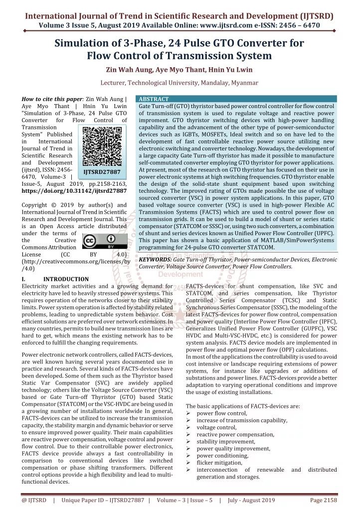
International Journal of Trend in Scientific Research and Development (IJTSRD) Volume 3 Issue 5, August 2019 Available Online: www.ijtsrd.com e-ISSN: 2456 – 6470 Simulation of 3-Phase, 24 Pulse GTO Converter for Flow Control of Transmission System Zin Wah Aung, Aye Myo Thant, Hnin Yu Lwin Lecturer, Technological University, Mandalay, Myanmar How to cite this paper: Zin Wah Aung | Aye Myo Thant | Hnin Yu Lwin "Simulation of 3-Phase, 24 Pulse GTO Converter for Flow Transmission System" Published in International Journal of Trend in Scientific Research and Development (ijtsrd), ISSN: 2456- 6470, Volume-3 | Issue-5, August 2019, pp.2158-2163, https://doi.org/10.31142/ijtsrd27887 Copyright © 2019 by author(s) and International Journal of Trend in Scientific Research and Development Journal. This is an Open Access article distributed under the terms of the Creative Commons Attribution License (CC (http://creativecommons.org/licenses/by /4.0) I. INTRODUCTION Electricity market activities and a growing demand for electricity have led to heavily stressed power systems. This requires operation of the networks closer to their stability limits. Power system operation is affected by stability related problems, leading to unpredictable system behavior. Cost efficient solutions are preferred over network extensions. In many countries, permits to build new transmission lines are hard to get, which means the existing network has to be enforced to fulfill the changing requirements. Power electronic network controllers, called FACTS-devices, are well known having several years documented use in practice and research. Several kinds of FACTS-devices have been developed. Some of them such as the Thyristor based Static Var Compensator (SVC) are awidely applied technology; others like the Voltage Source Converter (VSC) based or Gate Turn-off Thyristor (GTO) based Static Compensator (STATCOM) or the VSC-HVDC are being used in a growing number of installations worldwide In general, FACTS-devices can be utilized to increase the transmission capacity, the stability margin and dynamic behavior or serve to ensure improved power quality. Their main capabilities are reactive power compensation, voltage control and power flow control. Due to their controllable power electronics, FACTS device provide always a fast controllability in comparison to conventional devices like switched compensation or phase shifting transformers. Different control options provide a high flexibility and lead to multi- functional devices. ABSTRACT Gate Turn-off (GTO) thyristor based power control controller for flow control of transmission system is used to regulate voltage and reactive power improment. GTO thyristor switching devices with high-power handling capability and the advancement of the other type of power-semiconductor devices such as IGBTs, MOSFETs, Ideal switch and so on have led to the development of fast controllable reactive power source utilizing new electronic switching and converter technology. Nowadays, the development of a large capacity Gate Turn-off thyristor has made it possible to manufacture self-commutated converter employing GTO thyristor for power applications. At present, most of the research on GTO thyristor has focused on their use in power electronic systems at high switching frequencies. GTO thyristor enable the design of the solid-state shunt equipment based upon switching technology. The improved rating of GTOs made possible the use of voltage sourced converter (VSC) in power system applications. In this paper, GTO based voltage source converter (VSC) is used in high-power Flexible AC Transmission Systems (FACTS) which are used to control power flow on transmission grids. It can be used to build a model of shunt or series static compensator (STATCOM or SSSC) or, using two such converters, a combination of shunt and series devices known as Unified Power Flow Controller (UPFC). This paper has shown a basic application of MATLAB/SimPowerSystems programming for 24-pulse GTO converter STATCOM. KEYWORDS: Gate Turn-off Thyristor, Power-semiconductor Devices, Electronic Converter, Voltage Source Converter, Power Flow Controllers. FACTS-devices for shunt compensation, like SVC and STATCOM, and series compensation, like Thyristor Controlled Series Compensator (TCSC) and Static Synchronous Series Compensator (SSSC), the modeling of the latest FACTS-devices for power flow control, compensation and power quality (Interline Power Flow Controller (IPFC), Generalizes Unified Power Flow Controller (GUPFC), VSC HVDC and Multi-VSC-HVDC, etc.) is considered for power system analysis. FACTS device models are implemented in power flow and optimal power flow (OPF) calculations. In most of the applications the controllability is used to avoid cost intensive or landscape requiring extensions of power systems, for instance like upgrades or additions of substations and power lines. FACTS-devices provide a better adaptation to varying operational conditions and improve the usage of existing installations. The basic applications of FACTS-devices are: power flow control, increase of transmission capability, voltage control, reactive power compensation, stability improvement, power quality improvement, power conditioning, flicker mitigation, interconnection generation and storages. Control of IJTSRD27887 BY 4.0) of renewable and distributed @ IJTSRD | Unique Paper ID – IJTSRD27887 | Volume – 3 | Issue – 5 | July - August 2019 Page 2158
International Journal of Trend in Scientific Research and Development (IJTSRD) International Journal of Trend in Scientific Research and Development (IJTSRD) @ www.ijtsrd.com www.ijtsrd.com eISSN: 2456-6470 POWER ELECTRONIC SEMICONDUCTORS POWER ELECTRONIC SEMICONDUCTORS Power electronics have a widely spread range of applications from electrical machine drives to excitation systems, industrial high current rectifiers for metal smelters, frequency controllers or electrical trains. FACTS-devices are ide others, but use the same technology trends. It has started with the first Thyristor rectifiers in 1965 and goes to the nowadays modularized III. Power electronics have a widely spread range of applications from electrical machine drives to excitation systems, industrial high current rectifiers for metal smelters, frequency controllers or electrical trains. FACTS just one application beside others, but use the same technology trends. It has started with the first Thyristor rectifiers in 1965 and goes to the nowadays modularized IGBT or IGCT voltage source converters. IGBT or IGCT voltage source converters. In all applications the practical requirements, needs and benefits have to be considered carefully to justify the investment into a complex new device. The usage of lines for active power transmission should be ideally up to the thermal limits. Voltage and stability limits shall be shifted with the means of the several different FACTS d be seen that with growing line length, the opportunity for FACTS devices gets more and more important. The influence of FACTS-devices is achieved through switched or controlled shunt compensation, series compensation or phase shift control. The devices work electrically as fast current, voltage or impedance controllers. The power electronic allows very short reaction times down to far below one second. II. POWER FLOW CONTROLLER DEVICES The development of FACTS-devices has started with the growing capabilities of power electronic components. Devices for high power levels have been made available in converters for high and even highest voltage levels. The overall starting points are network elements influencing the reactive power or the impedance of a part of the power system. The term 'dynamic' is used to express the fast controllability of FACTS-devices provided by the power electronics. This is one of the main differentiation factors from the conventional devices. The term 'static' means that the devices have no moving parts like mechanical switches to perform the dynamic controllability. Therefore most of the FACTS devices can equally be static and dynamic. The left column in Fig(1) contains the conventional devices built out of fixed or mechanically switchable components like resistance, inductance or capacitance together with transformers. The FACTS-devices contain these elements as well but use additional power electronic valves or converters to switch the elements in smaller steps or with sw patterns within a cycle of the alternating current. The left column of FACTS-devices uses Thyristor valves or converters. These valves or converters are well known since several years. They have low losses because of their low switching frequency of once a cycle in the converters or the usage of the Thyristors to simply bridge impedances in the valves. The right column of FACTS-devices contains more advanced technology of voltage source converters based today mainly on Insulated Gate Bipolar Transistors (IGBT) or Insulated Gate Commutated Thyristors (IGCT). Voltage Source Converters provide a free controllable voltage in magnitude and phase due to a pulse width modulation of the IGBTs or IGCTs. High modulation frequencies allow to get low harmonics in the output signal and even to compensate disturbances coming from the network. The disadvantage is that with an increasing switching frequency, the losses are increasing as well. Therefore special designs of the converters are required to compensate thi In each column the elements can be structured according to their connection to the power system. The shunt devices are primarily for reactive power compensation and therefore voltage control. The SVC provides in comparison to the mechanically switched compensation a smoother and more precise control. It improves the stability of the network and it can be adapted instantaneously to new situations. The STATCOM goes one step further and is capable of improving the power quality against even dips and flicke the power quality against even dips and flickers. In all applications the practical requirements, needs and idered carefully to justify the investment into a complex new device. The usage of lines for active power transmission should be ideally up to the thermal limits. Voltage and stability limits shall be shifted with the means of the several different FACTS devices. It can be seen that with growing line length, the opportunity for FACTS devices gets more and more important. The influence devices is achieved through switched or controlled shunt compensation, series compensation or phase shift The devices work electrically as fast current, voltage or impedance controllers. The power electronic allows very short reaction times down to far below one second. POWER FLOW CONTROLLER DEVICES devices has started with the g capabilities of power electronic components. Devices for high power levels have been made available in converters for high and even highest voltage levels. The overall starting points are network elements influencing the f a part of the power Fig2. Ranges of converter voltages and power of Fig2. Ranges of converter voltages and power of applications for power applications for power semiconductors [2] The term 'dynamic' is used to express the fast controllability devices provided by the power electronics. This is one of the main differentiation factors from the conventional Thyristor is a device, which can be triggered with a pulse at the gate and remains in the on zero crossing. Therefore only one switching per half possible, which limits the controllability. highest current and blocking voltage. This means that fewer semiconductors need to be used for an application. Thyristors are used as switches for capacities or inductances, in converters for reactive power compensators or as protection switch for less robust power converters. Thyristors are still the devices for applications with the highest voltage and power levels. They are part of the mostly used FACTS-devices up to the biggest HVDC with a voltage level above 500 kV an MVA. To increase the controllability, GTO developed, which can be switched off with a voltage peak at the gate. These devices are nowadays replaced by Insulated Gate Commutated Thyristors (IGCT), which combine the advantage of the Thyristor, the low on stage losses, with low switching losses. These semiconductors are used in smaller FACTS and drive applications. The Insulated Gate Bipolar Transistor (IGBT) is getting more and more importance in the FACTS area. An IGBT can be switched on with a positive voltage and switched off with a zero voltage. This allows a very simple gate drive unit to control the IGBT. The voltage and power level of the applications is on the way to grow up to 300 kV and 1000 MVA for HVDC with Voltage Source Converters. The IGBT capability covers nowadays the whole range of power system applications. An important issue for power semiconductors is the packaging to ensure a reliable connection to the gate drive unit. This electronic circ ensures beside the control of the semiconductor as well its supervision and protection. A development in the Thyristor area tries to trigger the Thyristor with a light signal through an optical fiber. This allows the decoupling of the Semiconductor and the gate[2]. the gate[2]. Thyristor is a device, which can be triggered with a pulse at the gate and remains in the on-stage until the next current zero crossing. Therefore only one switching per half-cycle is possible, which limits the controllability. Thyristors have the highest current and blocking voltage. This means that fewer semiconductors need to be used for an application. Thyristors are used as switches for capacities or inductances, in converters for reactive power compensators or as switch for less robust power converters. e devices have no moving parts like mechanical switches to perform the dynamic controllability. Therefore most of the FACTS- devices can equally be static and dynamic. (1) contains the conventional devices ically switchable components like resistance, inductance or capacitance together with devices contain these elements as well but use additional power electronic valves or converters to switch the elements in smaller steps or with switching patterns within a cycle of the alternating current. The left devices uses Thyristor valves or converters. These valves or converters are well known since several years. They have low losses because of their low f once a cycle in the converters or the usage of the Thyristors to simply bridge impedances in the Thyristors are still the devices for applications with the highest voltage and power levels. They are part of the mostly devices up to the biggest HVDC-Transmissions with a voltage level above 500 kV and power above 3000 To increase the controllability, GTO-Thyristors have been developed, which can be switched off with a voltage peak at the gate. These devices are nowadays replaced by Insulated Gate Commutated Thyristors (IGCT), which combine the dvantage of the Thyristor, the low on stage losses, with low devices contains more advanced technology of voltage source converters based today mainly stors (IGBT) or Insulated Gate Commutated Thyristors (IGCT). Voltage Source Converters provide a free controllable voltage in magnitude and phase due to a pulse width modulation of the IGBTs or IGCTs. High modulation frequencies allow to get low in the output signal and even to compensate disturbances coming from the network. The disadvantage is that with an increasing switching frequency, the losses are increasing as well. Therefore special designs of the converters are required to compensate this. These semiconductors are used in smaller FACTS-devices and drive applications. The Insulated Gate Bipolar Transistor (IGBT) is getting more and more importance in the FACTS a. An IGBT can be switched on with a positive voltage and switched off with a zero voltage. This allows a very simple gate drive unit to control the IGBT. The voltage and power level of the applications is on the way to grow up to 300 kV VDC with Voltage Source Converters. In each column the elements can be structured according to their connection to the power system. The shunt devices are primarily for reactive power compensation and therefore voltage control. The SVC provides in comparison to the compensation a smoother and more precise control. It improves the stability of the network and it can be adapted instantaneously to new situations. The STATCOM goes one step further and is capable of improving The IGBT capability covers nowadays the whole range of power system applications. An important issue for power semiconductors is the packaging to ensure a reliable connection to the gate drive unit. This electronic circuit ensures beside the control of the semiconductor as well its supervision and protection. A development in the Thyristor area tries to trigger the Thyristor with a light signal through an optical fiber. This allows the decoupling of the @ IJTSRD | Unique Paper ID – IJTSRD27887 27887 | Volume – 3 | Issue – 5 | July - August 20 August 2019 Page 2159
International Journal of Trend in Scientific Research and Development (IJTSRD) International Journal of Trend in Scientific Research and Development (IJTSRD) @ www.ijtsrd.com www.ijtsrd.com eISSN: 2456-6470 IV. OPERATION PRINCIPLES OF STATCOM FOR POWER FLOW ANALYSIS A STATCOM is usually used to control transmission voltage by reactive power shunt compensation. Typically, a STATCOM consists of a coupling transformer, an GTO based inverter and a DC capacitor, which is shown in such an arrangement, in ideal steady state analysis, it can be assumed that the active power exchange between the AC system and the STATCOM can be neglected, and only the reactive power can be exchanged between them. Based on the operating principle of the STATCOM, the equivalent circuit can be derived, which is given in Fig OPERATION PRINCIPLES OF STATCOM FOR SIMULINKS OF THREE CONVERTER MODEL Three-phase 24-pulse GTO converter shown in GTO switch and zig-zag phase shifting transformers to build a GTO-type 100 MVA, 132 kV voltage source inverter. This type of converter is used in high MVA) Flexible AC Transmission Systems (FACTS) which are used to control power flow on transmission grids. It can be used, for example, to build a model of shunt or series static compensator (STATCOM or SS converters, a combination of shunt and series devices known as Unified Power Flow Controller (UPFC). The inverter described in three-phase 24 harmonic neutralized. SIMULINKS OF THREE-PHASE 24-PULSES GTO CONVERTER MODEL pulse GTO converter shown in Fig5 uses zag phase shifting transformers to build type 100 MVA, 132 kV voltage source inverter. type of converter is used in high-power (up to 200 MVA) Flexible AC Transmission Systems (FACTS) which are used to control power flow on transmission grids. It can be used, for example, to build a model of shunt or series static compensator (STATCOM or SSSC) or, using two such converters, a combination of shunt and series devices known as Unified Power Flow Controller (UPFC). The inverter phase 24-pulse GTO converter is a VI. A STATCOM is usually used to control transmission voltage by reactive power shunt compensation. Typically, a STATCOM consists of a coupling transformer, an GTO based inverter and a DC capacitor, which is shown in Fig(3). For teady state analysis, it can be assumed that the active power exchange between the AC system and the STATCOM can be neglected, and only the reactive power can be exchanged between them. Based on the operating principle of the STATCOM, the equivalent Fig(3)[9]. Fig3. STATCOM equivalent circuit 3. STATCOM equivalent circuit [9] In the derivation, it is assumed that (a) harmonics generated by the STATCOM are neglected; (b) the system as well as the STATCOM are three phase balanced. Then the STA be equivalently represented by a controllable fundamental frequency positive sequence voltage source V the STATCOM output voltage can be regulated such that the reactive power of STATCOM can be changed. V. DESIGN CALCULATIONS OF THREE PULSES GTO CONVERTER 24-pulse converter is obtained combining two 12 respectively, with an adequate phase shifted between them. For high power applications, the 24-pulse converter using filters tuned to the 23th - 25th harmonics. In the derivation, it is assumed that (a) harmonics generated by the STATCOM are neglected; (b) the system as well as the STATCOM are three phase balanced. Then the STATCOM can be equivalently represented by a controllable fundamental frequency positive sequence voltage source Vsh. In principle, the STATCOM output voltage can be regulated such that the reactive power of STATCOM can be changed. THREE-PHASE 24 pulse converter is obtained combining two 12-pulses VSI respectively, with an adequate phase shifted between them. pulse converter using Fig5. Three-phase 24-pulse GTO converter for simulation for simulation pulse GTO converter model VII. INSIDE MODEL OF 24 SOURCE CONVERTER The three-phase 24-pulse GTO’s voltage source converter (switch) is shown in Fig6. It consists of two 3 inverters and two phase-shifting transformers. INSIDE MODEL OF 24-PULSES GTO VOLTAGE SOURCE CONVERTER pulse GTO’s voltage source converter 6. It consists of two 3-phase, 3-level shifting transformers. DC bus voltage (Vdc = phase inverters. The two voltages generated by the inverters are applied to secondary windings of two zig shifting transformers connected in Wye (Y) or Delta (D). The two transformer primary win and the converter pulse patterns are phase shifted so that the two voltage fundamental components sum in phase on the primary side. Each 3-level inverter generates three square-wave voltages which can be +V of the +Vdc or –Vdc level (Sigma) can be adjusted between 0 and 180˚ from the Sigma input of the Firing Pulse Generator block. 9650 V) is connected to the two 3 9650 V) is connected to the two 3- phase inverters. The two voltages generated by the inverters are applied to secondary windings of two zig-zag phase- shifting transformers connected in Wye (Y) or Delta (D). The two transformer primary windings are connected in series and the converter pulse patterns are phase shifted so that the two voltage fundamental components sum in phase on level inverter generates three wave voltages which can be +Vdc, 0, -Vdc. The duration level (Sigma) can be adjusted between 0 ˚ from the Sigma input of the Firing Pulse Generator Fig4. 24-pulse STATCOM [10] [10] @ IJTSRD | Unique Paper ID – IJTSRD27887 27887 | Volume – 3 | Issue – 5 | July - August 20 August 2019 Page 2160
International Journal of Trend in Scientific Research and Development (IJTSRD) International Journal of Trend in Scientific Research and Development (IJTSRD) @ www.ijtsrd.com www.ijtsrd.com eISSN: 2456-6470 SIMULATION RESULT OF THREE-PHASE 24- PULSES GTO CONVERTER Start the simulation. Simulation Results Vabc(pu), ab Converter of Three-phase 24- VIII. SIMULATION RESULT OF THREE PULSES GTO CONVERTER Start the simulation. Simulation Results V Iabc(pu/100MVA) and Van Vab pulse GTO Converter is shown in pulse GTO Converter is shown in Fig8. Fig6. Inside model of 24-pulse GTO’s voltage source converter pulse GTO’s voltage source Each inverter uses a Three-Level Bridge block where specified power electronic devices are GTO thyristor switches. In this model each leg of the inverter uses 3 GTO thyristor switches to obtain the 3 voltage levels (+V Vdc). Despite this simplified switch arrangement, the model still requires 2 pulses per arm as in the physical model. still requires 2 pulses per arm as in the physical model. Level Bridge block where specified power electronic devices are GTO thyristor switches. In this model each leg of the inverter uses 3 GTO thyristor switches to obtain the 3 voltage levels (+Vdc, 0, – switch arrangement, the model Fig8. Simulation results V and Van, Vab of three-phase 24 8. Simulation results Vabc(pu), Iabc (pu/100MVA) phase 24-pulse GTO converter Voltages generated by the inverter (trace 1), load currents (trace 2), phase-neutral voltage and phase one of the four inverters (1Y) superimposed on trace 3. When the inverter is operating at no load, can be observe the three 24-step voltage waveform. When the load is switched on the voltage becomes smoother because harmonics are filtered by the transformer leakage reactances. filtered by the transformer leakage reactances. Voltages generated by the inverter (trace 1), load currents neutral voltage and phase-phase voltage of one of the four inverters (1Y) superimposed on trace 3. When the inverter is operating at no load, can be observe the age waveform. When the load is switched on the voltage becomes smoother because harmonics are Fig7. Inside model of firing pulse generator 7. Inside model of firing pulse generator The pulse pattern sent to each leg of a 3-phase inverter is described inside the Firing Pulse Generator shown in The phase shifts produced by the secondary delta connections (-30 degrees) and by the primary zig connections (+7.5 degrees for transformers 1Y and 1D, and 7.5 degrees for transformers 2Y and 2D) allows to neutralize harmonics up to 23th harmonic. The 30-degree phase between the Y and D secondaries cancels harmonics 5+12n (5, 17, 29, 41, ...) and 7+12n (7, 19, 31, 43, ...). In addition, the 15-degree phase shift between the two groups of transformers (1Y and 1D leading by 7.5˚, 2Y and 2D laggi by +7.5˚) allows cancellation of harmonics 11+24n (11, 35, ...) and 13+24n (13, 37, ...). Considering that all 3n the harmonics are not transmitted by the Y and D secondaries, the first harmonic which are not cancelled by the transformers are 23rd, 25th choosing an appropriate conduction angle for the 3 inverters (sigma = 180 – 15 = 165 degrees), the 23 can be minimized. The first significant harmonics are therefore the 23 25th. This type of inverter generates an almost sinusoid al waveform consisting of 24-steps.The inverter is operated in open loop at constant DC voltage. phase inverter is described inside the Firing Pulse Generator shown in Fig7. The phase shifts produced by the secondary delta 30 degrees) and by the primary zig-zag connections (+7.5 degrees for transformers 1Y and 1D, and - 7.5 degrees for transformers 2Y and 2D) allows to neutralize degree phase-shift between the Y and D secondaries cancels harmonics 5+12n (5, 17, 29, 41, ...) and 7+12n (7, 19, 31, 43, ...). In addition, the degree phase shift between the two groups of ˚, 2Y and 2D lagging ˚) allows cancellation of harmonics 11+24n (11, 35, Considering that all 3n the harmonics are not transmitted by the Y and D secondaries, the first harmonic which are not th, 47th and 49th. By choosing an appropriate conduction angle for the 3-level 15 = 165 degrees), the 23rd and 25th The first significant harmonics are therefore the 23th and generates an almost sinusoid al steps.The inverter is operated in Fig9. Total harmonic distortion of V phase 24-pulse GTO converter pulse GTO converter 9. Total harmonic distortion of Vabc(pu) in three- @ IJTSRD | Unique Paper ID – IJTSRD27887 27887 | Volume – 3 | Issue – 5 | July - August 20 August 2019 Page 2161
International Journal of Trend in Scientific Research and Development (IJTSRD) International Journal of Trend in Scientific Research and Development (IJTSRD) @ www.ijtsrd.com www.ijtsrd.com eISSN: 2456-6470 Once the simulation is completed, open the Powergui and select "FFT Analysis" to display the 0~ 4000 Hz frequency spectrum of signals saved in the two "psb24pulse_str" structure. Select signal labeled “Vabc(pu)”. The FFT will be performed on a 1-cycle window of phase A voltage starting at t = 0.025–1/60 s (inverter operating at no load). Sigma = 180 * (1- 1/n) ed, open the Powergui and FFT Analysis tool of Powergui shows total harmonic phase GTO converter using GTO/Diode in Figs 9, 10 and 11. The total harmonic distortion (THD) of Vabc pulse GTO converter is 13.75 % in (pu/100MVA) and Van, Vab converter 1Y is 138.69 % and 43.31 % in Fig10 and Fig11. FFT Analysis tool of Powergui shows total harmonic distortion of three-phase GTO converter using GTO/Diode in Figs 9, 10 and 11. The total harmonic distortion (THD) of V (pu) in three-phase 24-pulse GTO converter is 13.75 % in Fig9. And the THD of Iabc (pu/100MVA) and V 1Y is 138.69 % and 43.31 % in IX. CONCLUSION GTO converter STATCOM compensation is considering the length and kind of transmiss magnitude of the load, and the duration and magnitude of the voltage variation. The simplest three-phase converter is the six converter however even at low rating a simple six pulse converter is unlikely in high power harmonic distortion. To reduce the harmonic distortion to an acceptable level the pulse order must be increased to 24 48-pulse. To get the 24-pulse converter complex phase shifting transformers are needed but an approximate behaviour can be obtained using simple 12 transformers; two 12-pulse transformers having relative phase displacements of 15◦, quasi 24 quasi 24-pulse operation allows a small circulation of 12 and 24- pulse order harmonic due to th which are characteristic of each 12 perfectly cancelled, but the residual magnitude is acceptably small. From the simulation results, test results are obtained by using the FFT (First Fourier Transformer) tool Powergui, it can be seen that the total harmonic distortion (THD) of three-phase 24-pulse GTO converter. When the load is switched on the voltage becomes smoother because harmonics are filtered by the transformer leakage reactances. This paper covers knowledge of STATCOM for power system operation, power flow control, reactive power compensation and voltage control problems for power engineers. ACKNOWLEDGEMENT The author wishes to thank to Dr.Yadana Aung, Professor and Head, Department of Electrical Power Engineering, Technological University (Mandalay). REFERENCES [1]L. Gyugyi, 1979, “Reactive Power Generation and Control by Thyristor Circuits,” IEEE Trans. on Industry Applications. select "FFT Analysis" to display the 0~ 4000 Hz frequency spectrum of signals saved in the two "psb24pulse_str" (pu)”. The FFT will be cycle window of phase A voltage starting 1/60 s (inverter operating at no load). GTO converter STATCOM compensation is considering the length and kind of transmission line, the power factor and magnitude of the load, and the duration and magnitude of phase converter is the six-pulse converter however even at low rating a simple six pulse converter is unlikely in high power applications due to its harmonic distortion. To reduce the harmonic distortion to an acceptable level the pulse order must be increased to 24- or pulse converter complex phase- shifting transformers are needed but an approximate aviour can be obtained using simple 12-pulse pulse transformers having relative , quasi 24-pulse operation. The pulse operation allows a small circulation of 12- pulse order harmonic due to the 12-pulse harmonics which are characteristic of each 12-pulse converter are not perfectly cancelled, but the residual magnitude is acceptably From the simulation results, test results are obtained by using the FFT (First Fourier Transformer) tool of the Powergui, it can be seen that the total harmonic distortion pulse GTO converter. When the load is switched on the voltage becomes smoother because harmonics are filtered by the transformer leakage Fig10. Total harmonic distortion of Iabc in three-phase 24-pulse GTO converter abc (pu/100MVA) pulse GTO converter rs knowledge of 24-pulse GTO converter for power system operation, power flow control, reactive power compensation and voltage control problems The author wishes to thank to Dr.Yadana Aung, Professor Head, Department of Electrical Power Engineering, Technological University (Mandalay). L. Gyugyi, 1979, “Reactive Power Generation and Control by Thyristor Circuits,” IEEE Trans. on Industry [2]Rolf Rolf Thorvaldsson, Grünbaum, Grünbaum, Åke Åke Petersson “FACTS, “FACTS, Petersson and and Björn the the Björn Thorvaldsson, performance of electrical grids”, ABB Review. performance of electrical grids”, ABB Review. 2003, 2003, Improving Improving [3]N. Hingorani, L. Gyugyi, 2000, “Understanding FACTS, Concepts and Technology of Flexible AC Transmission Systems,” IEEE Press, New York. Systems,” IEEE Press, New York. N. Hingorani, L. Gyugyi, 2000, “Understanding FACTS, Concepts and Technology of Flexible AC Transmission [4]Dr. Xiao-Ping Zhang, Bikash Pa Rehtanz., 2006, “Modelling and Control of Flexible AC Transmission System”, Heidelberg, Germany. Ping Zhang, Bikash Pal and Dr. Christian Rehtanz., 2006, “Modelling and Control of Flexible AC Transmission System”, Springer Springer-Verlag Berlin [5]R. Mohan Mathur, Rajiv K. Varma, 2002, “Thyristor based FACTS Controllers for Electrical Transmission based FACTS Controllers for Electrical Transmission R. Mohan Mathur, Rajiv K. Varma, 2002, “Thyristor- Fig11. Total harmonic distortion of Van 1Y in three-phase 24-Pulse GTO converter an, Vab converter Pulse GTO converter @ IJTSRD | Unique Paper ID – IJTSRD27887 27887 | Volume – 3 | Issue – 5 | July - August 20 August 2019 Page 2162
International Journal of Trend in Scientific Research and Development (IJTSRD) @ www.ijtsrd.com eISSN: 2456-6470 Systems”, by the Institute of Electrical and Electronics Engineers, Inc. , A John Wiley & Sons, Inc. USA. [8]K. K. Sen, 1999, “STATCOM, STATic synchronous COMpensator: Theory, Modeling and Applications”, IEEE Transaction on Power Delivery, Vol. 2. [6]Ricardo Dávalos Marín, 2004, “Detailed Analysis of Multi-pulse STATCOM”, Ph. D Thesis, University of Toronto. [9]E. Larsen, N. Miller, S. Nilsson and S. Lindgren, 1998, “Benefits of GTO-based Compensation Systems for Electric Utility Applications”, IEEE Transaction on Power Delivery, Vol. 7. [7]Paulo F. Ribeiro, 2004, “Transmission Power Quality Benefits Realized by FACTS Contrtoller”, BWX Technologies, Inc, Lynchburg. [10]Siriroj Sirisukprasert, 2004, “Modeling and Control of a Cascaded-Multilevel Converter-Based STATCOM”, Blacksburg, Virginia Polytechnic Institute and State University, USA. @ IJTSRD | Unique Paper ID – IJTSRD27887 | Volume – 3 | Issue – 5 | July - August 2019 Page 2163