Download
1 / 6
60 likes | 66 Views
In modern times, due to the increasing demand for energy as the transmission network expands, the transmission line must operate under a loaded condition and there is a risk of current drain control and voltage instability. This document proposes the control of energy in a network of power supply systems by including TCSC and SVC devices. The TCSC is a series compensated device to reduce the reactance of the transmission line to improve the current through it, while the SVC is a bypass compensated device and improves the voltage profile. This article presents a systematic procedure for modeling and simulation with MATLAB SIMULINK set of blockers for the Simpower system . The optimal location of the TCSC and SVC device is considered for the control of the power flow and the voltage stability limit. The proposed approach is implemented in an 11 state test system model of four two state machines and the simulated result is presented to validate the proposed test case system. In this paper performance of TCSC and SVC, the device is analyzed and compared with the simulated result for better control of the power flow in the power system. Mr. Gautam Shah | Mr. Durgesh Vishwakarma "Power Flow Control in Power System using Thyristor Controlled Series Capacitor (TCSC)" Published in International Journal of Trend in Scientific Research and Development (ijtsrd), ISSN: 2456-6470, Volume-3 | Issue-5 , August 2019, URL: https://www.ijtsrd.com/papers/ijtsrd25197.pdf Paper URL: https://www.ijtsrd.com/engineering/electrical-engineering/25197/power-flow-control-in-power-system-using-thyristor-controlled-series-capacitor-tcsc/mr-gautam-shah<br>

E N D
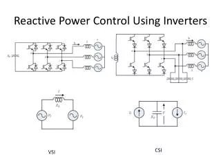
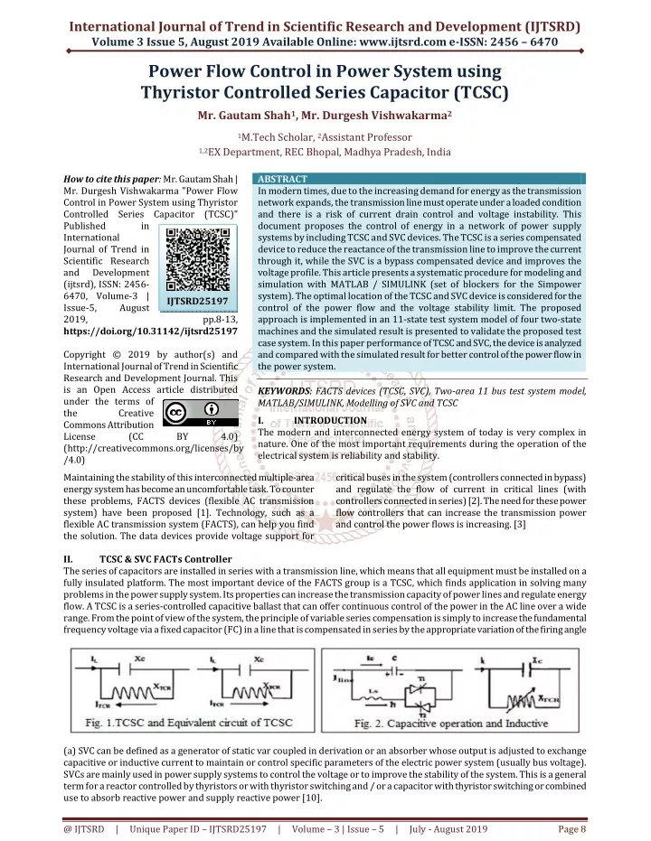
International Journal of Trend in Scientific Research and Development (IJTSRD) Volume 3 Issue 5, August 2019 Available Online: www.ijtsrd.com e-ISSN: 2456 – 6470 Power Flow Control in Power System using Thyristor Controlled Series Capacitor (TCSC) Mr. Gautam Shah1, Mr. Durgesh Vishwakarma2 1M.Tech Scholar, 2Assistant Professor 1,2EX Department, REC Bhopal, Madhya Pradesh, India How to cite this paper: Mr. Gautam Shah | Mr. Durgesh Vishwakarma "Power Flow Control in Power System using Thyristor Controlled Series Capacitor (TCSC)" Published in International Journal of Trend in Scientific Research and Development (ijtsrd), ISSN: 2456- 6470, Volume-3 | Issue-5, August 2019, https://doi.org/10.31142/ijtsrd25197 Copyright © 2019 by author(s) and International Journal of Trend in Scientific Research and Development Journal. This is an Open Access article distributed under the terms of the Creative Commons Attribution License (CC (http://creativecommons.org/licenses/by /4.0) Maintaining the stability of this interconnected multiple-area energy system has become an uncomfortable task. To counter these problems, FACTS devices (flexible AC transmission system) have been proposed [1]. Technology, such as a flexible AC transmission system (FACTS), can help you find the solution. The data devices provide voltage support for II. TCSC & SVC FACTs Controller The series of capacitors are installed in series with a transmission line, which means that all equipment must be installed on a fully insulated platform. The most important device of the FACTS group is a TCSC, which finds application in solving many problems in the power supply system. Its properties can increase the transmission capacity of power lines and regulate energy flow. A TCSC is a series-controlled capacitive ballast that can offer continuous control of the power in the AC line over a wide range. From the point of view of the system, the principle of variable series compensation is simply to increase the fundamental frequency voltage via a fixed capacitor (FC) in a line that is compensated in series by the appropriate variation of the firing angle ABSTRACT In modern times, due to the increasing demand for energy as the transmission network expands, the transmission line must operate under a loaded condition and there is a risk of current drain control and voltage instability. This document proposes the control of energy in a network of power supply systems by including TCSC and SVC devices. The TCSC is a series compensated device to reduce the reactance of the transmission line to improve the current through it, while the SVC is a bypass compensated device and improves the voltage profile. This article presents a systematic procedure for modeling and simulation with MATLAB / SIMULINK (set of blockers for the Simpower system). The optimal location of the TCSC and SVC device is considered for the control of the power flow and the voltage stability limit. The proposed approach is implemented in an 11-state test system model of four two-state machines and the simulated result is presented to validate the proposed test case system. In this paper performance of TCSC and SVC, the device is analyzed and compared with the simulated result for better control of the power flow in the power system. KEYWORDS: FACTS devices (TCSC, SVC), Two-area 11 bus test system model, MATLAB/SIMULINK, Modelling of SVC and TCSC I. INTRODUCTION The modern and interconnected energy system of today is very complex in nature. One of the most important requirements during the operation of the electrical system is reliability and stability. critical buses in the system (controllers connected in bypass) and regulate the flow of current in critical lines (with controllers connected in series) [2]. The need for these power flow controllers that can increase the transmission power and control the power flows is increasing. [3] IJTSRD25197 pp.8-13, BY 4.0) (a) SVC can be defined as a generator of static var coupled in derivation or an absorber whose output is adjusted to exchange capacitive or inductive current to maintain or control specific parameters of the electric power system (usually bus voltage). SVCs are mainly used in power supply systems to control the voltage or to improve the stability of the system. This is a general term for a reactor controlled by thyristors or with thyristor switching and / or a capacitor with thyristor switching or combined use to absorb reactive power and supply reactive power [10]. @ IJTSRD | Unique Paper ID – IJTSRD25197 | Volume – 3 | Issue – 5 | July - August 2019 Page 8
International Journal of Trend in Scientific Research and Development (IJTSRD) @ www.ijtsrd.com eISSN: 2456-6470 III. To access the effectiveness of the developed SVC model, an 11-bus electrical power system, a two-area test system, an area 1 and a system 2 are used. Figure 3 shows the diagram of a single proposed line of 11 systems bus power supply with the SVC shunt fact device installed under consideration. TWO-AREA TEST SYSTEM MODEL WITH SVC FACT DEVICE Fig.3. Two-area Four-machine 11-bus power system with shunt FACT device SVC. All relevant parameters are listed in the appendix. The 13.8 kV source voltages are connected through a 290 km transmission line through three-phase step-up transformers. The system consists of two transformer output voltages of 500KV equivalent, 1000MVA and 4200MVA respectively in each area, connected by a 290 km transmission line. The loads in each 30KW area are selected to show the actual energy flow in the transmission line from area 1 to 2. The load center of approximately 60 kW is modeled where the active and reactive power absorbed by the load it is a function of the system voltage. IV. SIMULATION RESULTS OF SVC The SVC parameters of the control block represent the SVC susceptibility, the actual voltage and the measured value, and also the measured value of the reactive power SVC. In this thesis, the SVC only works in the voltage control mode and has obtained all the SVC data in this mode. It is shown in the following figures. The figure Variation of the SVC measure and the real value of B, V and Qm. The SVC FACT bypass device installed in the 11 bus system to find the active and reactive power supply in all the buses, the power in buses B1, B2, B3, B4, B5, B6, B7, B8, B9, B10 and B11 are calculated, the variations in the total active reactive power are shown in figure 4.3 figure 4.4 figure 4.5 and figure 4.6. Fig.4.1 Block represent Active power (P) of all buses and the sum of total power at buses (with SVC Connected at Bus 9) Fig.4.2 Variation of SVC measure and Actual value of susceptance (B), voltage (V) and reactive power (Qm). @ IJTSRD | Unique Paper ID – IJTSRD25197 | Volume – 3 | Issue – 5 | July - August 2019 Page 9
International Journal of Trend in Scientific Research and Development (IJTSRD) @ www.ijtsrd.com eISSN: 2456-6470 Fig.4.3 Active power (P) of all buses and sum of total active power at the buses with SVC connected at bus 9. Fig.4.4 Reactive power (Q) of all buses and sum of total reactive power at the buses if SVC Connected at Bus 9. Fig.4.5 Bus voltage control by SVC controller at different buses and sum of total voltage. Fig.4.6 Bus current of SVC device at different buses and sum of total bus current. V. The TCSC parameter blocks and the time curve show the TCSC voltage, the TCSC current, the active, reactive power, the TCSC impedance and the firing angle is an illustration in Figure 22. For the first 0, 5 s, the TCSC is canceled in 0.5 s The TCSC starts to control the impedance at 128Ω and this increases the power transfer, the TCSC starts with alpha at 900 to allow the least disturbance of commutation in the line. In this article, the TCSC only works in capacitive mode and initially controls the firing angle 900 from 0 to 0.5 seconds. After that it diminishes until 75.60 of 0.56 sec. At 2.5 sec. The capacitive mode starts in 2.5 to 5 seconds and the firing angle is constant and is maintained at this value 86.310, the TCSC impedance is 120.5Ω along the reference value. 120.80 is shown in Figure 5.1. SIMULATION RESULTS OF TCSC @ IJTSRD | Unique Paper ID – IJTSRD25197 | Volume – 3 | Issue – 5 | July - August 2019 Page 10
International Journal of Trend in Scientific Research and Development (IJTSRD) @ www.ijtsrd.com eISSN: 2456-6470 Fig. 5. TCSC parameter blocks. Fig.5.1. TCSC injected Active, Reactive Power and TCSC regulates the impedance with respect to firing angle. The TCSC device actually installed in the 11 bus system to find out the active power flow in all buses, the power in buses B1, B2, B3, B4, B5, B6, B7, B8, B9, B10, B11 , Btcsc is calculated and the total power improved by TCSC is 1730 MW as shown in figure 5.3 and in figure 5.4 Fig.5.2 Active power (P) of all buses and sum of total active power at the buses. Fig.5.3 Reactive power (Q) of all buses and sum of total reactive power at the buses. @ IJTSRD | Unique Paper ID – IJTSRD25197 | Volume – 3 | Issue – 5 | July - August 2019 Page 11
International Journal of Trend in Scientific Research and Development (IJTSRD) @ www.ijtsrd.com eISSN: 2456-6470 Fig.5.4 Graphical representation of bus voltage control by TCSC controller at different buses and sum of total voltage Fig. 5.5 Graphically represents the bus current at different buses and sum of all bus current. SUMMARY OF SIMULATED RESULTS The performance of the proposed model is analyzed and compared, when analyzing the TCSC the power flow in the transmission line that is active and the reactive power can improve 437.3 MW, 2911 MVA compared to SVC -24.35 MW, 1165 MVA, also the TCSC 7,919 kV transmission line voltage compared to the SVC device. All TCSC data is obtained in the capacitive operation mode and the SVC data is obtained only in the voltage control mode. According to the result, it has been found that in an SVC and TCSC device, that is, the TCSC controller is more effective in controlling voltage and power current in the power system network compared to the SVC controller. The bus data of the SVC and TCSC controller for Active, Reactive power, Voltage and current in the buses are shown in Table 1. TABLE1- COMPARISON BETWEEN TCSC AND SVC FOR P, Q, V AND I AT ALL THE BUSES SVC TCSC SVC TCSC SVC TCSC SVC TCSC BUSES P(MW) P(MW) Q (MVAR) Q (MVAR) V (kV) V (KV) I (KA) I (KA) B-1 -2.805 -120.3 45.39 -134.3 0.02848 0.02414 15.98 74.7 B-2 -8.044 -376.5 140.8 -414.8 0.02849 0.024 49.5 233.4 B-3 -3.327 111.7 34.25 318.6 0.02825 0.03305 12.18 102.2 B-4 -9.783 352.4 105 999.3 0.02827 0.03326 37.64 318.6 B-5 0.1773 -118.1 48.56 -128.6 1.035 0.8612 0.4691 202.7 B-6 1.104 -487.7 175.1 -540.5 1.038 0.8558 1.689 8.507 B-7 1.149 -487.4 465.8 -537.4 1.039 0.8472 1.597 8.563 B-8 0.5543 233.8 38.08 307.2 1.041 0.8012 0.3658 4.819 B-9 -1.309 482 319.5 701.9 1.029 0.7453 3.105 11.42 B-10 -1.347 481.3 1.29 133.3 1.028 1.229 1.255 11.53 B-11 0.3898 -115.9 -37.3 -329.7 1.027 1.221 0.3633 2.862 Btcsc - 482 - 1337 - 1.244 - 11.42 Total -24.35 437.3 1165 2911 7.348 7.919 124.1 778.6 @ IJTSRD | Unique Paper ID – IJTSRD25197 | Volume – 3 | Issue – 5 | July - August 2019 Page 12
International Journal of Trend in Scientific Research and Development (IJTSRD) @ www.ijtsrd.com eISSN: 2456-6470 [3]T.J.E. Miller, Reactive Power Control in Electric Systems, John Wiley (New York), 1982. VII. This article has been compared between the TCSC device and the SVC FACT device that is presented and discussed. In this way, a capacitive compensation of the series is used to reduce the reactive impedance of the series to minimize the variations of reception of the final voltage and the possibility of voltage failure and the power of the power supply line can be improved. In this article, an optimal positioning and sizing of the TCSC apparatus is proposed to improve and control the energy flows in the network to increase the energy flows in very charged lines. A simulation result of the MATLAB / SIMULINK model of an 11-way power system of four two- way machines with two controllers with TCSC shows the effectiveness of TCSC to control the active and reactive power through the transmission line. Therefore, it is concluded that the results were obtained with the TCSC and SVC device from the simulation; A proposed TCSC device model is suitable for active and reactive control of the power flow, and control of the transmission line voltage is better than the SVC device. REFERENCES [1]Narain G. Hingorani, ―Understanding FACTS, Concepts and Technology Of flexible AC Transmission Systems, by IEEE Press USA. CONCLUSION [4]R.M. Mathur, Editor, Static Compensators for Reactive Power Control, Canadian Electrical Association, Cantext Publications, Win- nipeg, 1984 [5]K.R. Padiyar and R.K. Verma, “Damping Torque Analysis of Static Var System Controllers", IEEE Trans., Power Systems, v.6, n.2, 1991, pp.458-465 [6]K.R.Padiyar and R.K.Verma, “Concepts of Static Var System Control for Enhancing Power Transfer in Long Transmission Lines", Electric machines and Power Systems, v.18, 1990, pp.337-358 [7]Electrical Power Systems Quality” by R.C Dugan, McGraw-Hill Companies. [8]Priyanka Kathal, Arti Bhandakkar “ Power Flow Control in Power System Using FACT Device Thyristor Controlled Series Capacitor (TCSC)” Department of Electrical and Electronics Engineering S.R.I.T Jabalpur, R.G.P.V University-Bhopal, India, IOSR Journal of Electrical and Electronics Engineering (IOSR-JEEE) e- ISSN: 2278-1676, p-ISSN: 2320-3331, Volume 7, Issue 6 (Sep. - Oct. 2013), PP 72-83. [2]P. Kundur, “Power System Stability and Control”, McGraw-Hill, 1994. @ IJTSRD | Unique Paper ID – IJTSRD25197 | Volume – 3 | Issue – 5 | July - August 2019 Page 13