Download
1 / 5
50 likes | 78 Views
Non linear loads are increasingly more abundant in commercial, residential and industrial sector and their percentage of the total load are growing steadily. The increasing uses of non linear loads are becoming more harmonic problems at utilities and customers sides. The harmonic problems cause damage of system equipment and low power quality. The most appropriate solution to mitigate this issue is passive filter. Passive filters are typically composed by inductors, capacitors and resistors which are used for mitigating harmonic distortions, power factor correction and improving power quality. In this paper, simulation models are implemented for mitigating harmonic distortions by applying passive filter at No 3 .Steel Mill Ywama, Yangon in distribution system. Passive filters are installing at point of common coupling PCC of 11kV feeder in distribution system to reduce the harmonic distortion within IEEE 519 1992 standards. THD is used as the harmonic index to study the effect of harmonic distortions. In this paper, the performance of the designed filter in this network and THD are obtained from simulation using MATLAB. Myo Win Kyaw | Hnin Yu Wai | Theingi Htun "Power Quality Improvement, Harmonic Elimination and Load Balancing in Industrial Power System" Published in International Journal of Trend in Scientific Research and Development (ijtsrd), ISSN: 2456-6470, Volume-3 | Issue-5 , August 2019, URL: https://www.ijtsrd.com/papers/ijtsrd26661.pdf Paper URL: https://www.ijtsrd.com/engineering/electrical-engineering/26661/power-quality-improvement-harmonic-elimination-and-load-balancing-in-industrial-power-system/myo-win-kyaw<br>

E N D
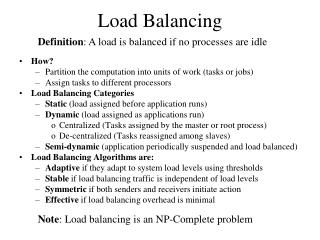
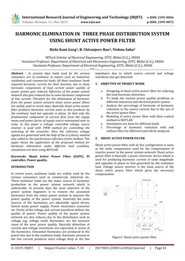
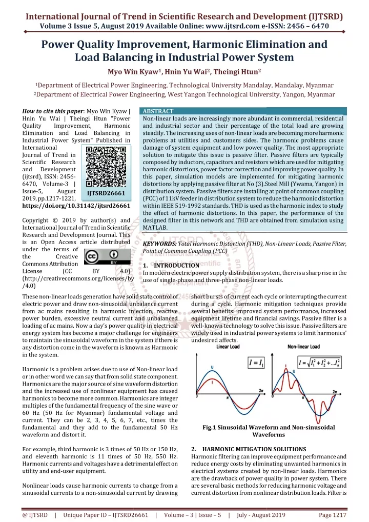
International Journal of Trend in Scientific Research and Development (IJTSRD) Volume 3 Issue 5, August 2019 Volume 3 Issue 5, August 2019 Available Online: www.ijtsrd.com e- Journal of Trend in Scientific Research and Development (IJTSRD) Journal of Trend in Scientific Research and Development (IJTSRD) -ISSN: 2456 – 6470 Power Quality Improvement, Harmonic Elimination Load Balancing Myo Win Kyaw Myo Win Kyaw1, Hnin Yu Wai2, Theingi Htun2 Power Quality Improvement, Harmonic Elimination Load Balancing in Industrial Power System n Industrial Power System Power Quality Improvement, Harmonic Elimination and 1Department of Electrical Power Engineering, Technological University Mandalay, 2Department of Electrical Power Engineering, West Yangon Technological University, Department of Electrical Power Engineering, West Yangon Technological University, Department of Electrical Power Engineering, West Yangon Technological University, Yangon, Myanmar Department of Electrical Power Engineering, Technological University Mandalay, Department of Electrical Power Engineering, Technological University Mandalay, Mandalay, Myanmar How to cite this paper: Myo Win Kyaw | Hnin Yu Wai | Theingi Htun "Power Quality Improvement, Elimination and Load Balancing in Industrial Power System" Published in International Journal of Trend in Scientific Research and Development (ijtsrd), ISSN: 2456- 6470, Volume-3 | Issue-5, August 2019, pp.1217-1221, https://doi.org/10.31142/ijtsrd26661 Copyright © 2019 by author(s) and International Journal of Trend in Scientific Research and Development Journal. This is an Open Access article distributed under the terms of the Creative Commons Attribution License (CC (http://creativecommons.org/licenses/by /4.0) These non-linear loads generation have solid state control of electric power and draw non-sinusoidal unbalance current from ac mains resulting in harmonic injection, reactive power burden, excessive neutral current and unbalanced loading of ac mains. Now a day’s power quality in electrical energy system has become a major challenge for engineers to maintain the sinusoidal waveform in the system if there is any distortion come in the waveform is known as Harmonic in the system. Harmonic is a problem arises due to use of Non or in other word we can say that from solid state component. Harmonics are the major source of sine waveform distortion and the increased use of nonlinear equipment has caused harmonics to become more common. Harmonics are in multiples of the fundamental frequency of the sine wave or 60 Hz (50 Hz for Myanmar) fundamental voltage and current. They can be 2, 3, 4, 5, 6, 7, etc., times the fundamental and they add to the fundamental 50 Hz waveform and distort it. For example, third harmonic is 3 times of 50 Hz or 150 Hz, and eleventh harmonic is 11 times of 50 Hz, 550 Hz. Harmonic currents and voltages have a detrimental effect on utility and end-user equipment. Nonlinear loads cause harmonic currents to change from sinusoidal currents to a non-sinusoidal current by drawing sinusoidal current by drawing ABSTRACT Non-linear loads are increasingly more abundant in commercial, residential and industrial sector and their percentage of the total load are growing steadily. The increasing uses of non-linear loads are becoming more harmonic problems at utilities and customers sides. The harmonic problems cause damage of system equipment and low power quality. The most appropriate solution to mitigate this issue is passive filter. Passive filters are composed by inductors, capacitors and resistors which are used for mitigating harmonic distortions, power factor correction and improving power quality. In this paper, simulation models are implemented for mitigating harmonic distortions by applying passive filter at No (3).Steel Mill (Ywama, Yangon) in distribution system. Passive filters are installing at point of common coupling (PCC) of 11kV feeder in distribution system to reduce the harmonic distortion within IEEE 519-1992 standards. THD is used as the harmonic index to study the effect of harmonic distortions. In this paper, the performance of the designed filter in this network and THD are obtained from simulation using MATLAB. KEYWORDS: Total Harmonic Distortion (THD), Non Point of Common Coupling (PCC) 1.INTRODUCTION In modern electric power supply distribution system, there is a sharp rise in the use of single-phase and three-phase non-linear loads. linear loads are increasingly more abundant in commercial, residential and industrial sector and their percentage of the total load are growing linear loads are becoming more harmonic problems at utilities and customers sides. The harmonic problems cause damage of system equipment and low power quality. The most appropriate solution to mitigate this issue is passive filter. Passive filters are typically composed by inductors, capacitors and resistors which are used for mitigating harmonic distortions, power factor correction and improving power quality. In this paper, simulation models are implemented for mitigating harmonic ying passive filter at No (3).Steel Mill (Ywama, Yangon) in distribution system. Passive filters are installing at point of common coupling (PCC) of 11kV feeder in distribution system to reduce the harmonic distortion Harmonic IJTSRD26661 used as the harmonic index to study the effect of harmonic distortions. In this paper, the performance of the designed filter in this network and THD are obtained from simulation using Total Harmonic Distortion (THD), Non-Linear Loads, Passive Filter, BY 4.0) In modern electric power supply distribution system, there is a sharp rise in the http://creativecommons.org/licenses/by linear loads. linear loads generation have solid state control of sinusoidal unbalance current from ac mains resulting in harmonic injection, reactive power burden, excessive neutral current and unbalanced day’s power quality in electrical energy system has become a major challenge for engineers to maintain the sinusoidal waveform in the system if there is any distortion come in the waveform is known as Harmonic short bursts of current each cycle or interrupting the current during a cycle. Harmonic mitigation techniques provide several benefits: improved system performance, increased nd financial savings. Passive filter is a known technology to solve this issue. Passive filters are widely used in industrial power systems to limit harmonics’ short bursts of current each cycle or interrupting the current during a cycle. Harmonic mitigation techniques provide several benefits: improved system performance, increased equipment lifetime and financial savings. Passive filter is a well-known technology to solve this issue. Passive filters are widely used in industrial power systems to limit harmonics’ undesired affects. due to use of Non-linear load or in other word we can say that from solid state component. Harmonics are the major source of sine waveform distortion and the increased use of nonlinear equipment has caused harmonics to become more common. Harmonics are integer multiples of the fundamental frequency of the sine wave or 60 Hz (50 Hz for Myanmar) fundamental voltage and current. They can be 2, 3, 4, 5, 6, 7, etc., times the fundamental and they add to the fundamental 50 Hz Fig.1 Sinusoidal Waveform and Non Waveforms Waveforms Sinusoidal Waveform and Non-sinusoidal 2.HARMONIC MITIGATION SOLUTIONS Harmonic filtering can improve equipment performance and reduce energy costs by eliminating unwanted harmonics in electrical systems created by non are the drawback of power quality in power system. There are several basic methods for reducing harmonic voltage and current distortion from nonlinear distribution loads. Filter is current distortion from nonlinear distribution loads. Filter is example, third harmonic is 3 times of 50 Hz or 150 Hz, and eleventh harmonic is 11 times of 50 Hz, 550 Hz. Harmonic currents and voltages have a detrimental effect on ATION SOLUTIONS Harmonic filtering can improve equipment performance and reduce energy costs by eliminating unwanted harmonics in electrical systems created by non-linear loads. Harmonics are the drawback of power quality in power system. There basic methods for reducing harmonic voltage and Nonlinear loads cause harmonic currents to change from a @ IJTSRD | Unique Paper ID – IJTSRD266 26661 | Volume – 3 | Issue – 5 | July - August 2019 August 2019 Page 1217
International Journal of Trend in Scientific Research and Development (IJTSRD) @ www.ijtsrd.com eISSN: 2456-6470 a method to reduce harmonics when the harmonic distortion has been increased in industrial plants. Harmonic filter minimize the thermal and electrical stress on the electrical infrastructure. It can improve phase current, voltage balance, the power quality and cost saving [3]. Two types of harmonic filters are Passive Filter, and Active Filter Among these methods, Passive Filters are applied to minimize harmonic distortions at No (3).Steel Mill (Ywama, Yangon) in this paper. Passive filters use a combination of reactors and capacitors to filter out harmonic frequencies. 3.PASSIVE FILTER One classical solution to mitigate power grid distortions is passive filters which can flow the harmonic distortions to a low impedance ground way in a parallel link or dissipate it at high impedance in a series connection. The function of passive filters is to absorb the load harmonic currents, preventing them from circulating through the electrical system [5].The aim of harmonic filters is to reduce the negative effects of harmonics in current or voltage. Passive filters are inductance, capacitance and resistance elements configured and tuned to control harmonics. Passive harmonic filters are the most commonly used filters in industry. Several parallel-connected branches of filters are required to reduce more than a number of harmonic orders. Passive filter are used in power systems for decreasing voltage distortion and for power factor correction [8]. Common type of passive filter configurations is shown in Fig.2. Classification of Passive Filter: Passive series filter Passive shunt filter Passive hybrid filter Techniques of passive Filters Single-Tuned filter High-pass filter( first, second or third order) 2nd order High-Pass 4.Case Study The No.3 Steel Mill (Ywama, Yangon) is chosen as case study area. This is located at Between Bayintnaung Road and Hlaing River, West Ywama Quarter, Insein Township, Yangon, Myanmar. It is produced many steel products such as Steel Billet (130×130×12,000mm Billets),Wire Nail, Barbed Wire, Square Mesh, Chain Link and Blade Wire. Since the dominant load of this No (3) Steel Mill (Ywama, Yangon) is industrial load. Most of the industrial loads are non-linear loads which cause malfunctioning of the loads connected at the PCC. Therefore, active filter can be used for minimizing the harmonic current injected at PCC by an industry of arc furnace. Incoming line of No (3) Steel Mill (Ywama,Yangon) is 66 kV bus bar of Hlawgar substation is stepped down by using 66 to 33kV transformer to 33kV. And then, 33kV voltage level is again stepped down to 11kV voltage level. In 11 kV main distribution feeder, two sections are separately operated as seen in Figure 5. 1st order High-Pass 3rd order High-Pass C–type Fig.4 Single Line Diagram of No (3) Steel Mill (Ywama, Yangon) The department EAF is operated at the 11kV (11MVA) bus bar. In fact, an electric arc furnace is a non-linear, time- varying load, which gives rise to harmonics. The electric arc itself is actually best represented as a source of voltage harmonics. The cause of harmonics is mainly related to the non-linear voltage-current characteristic of the arc while the voltage fluctuations are due to the arc length changes that occur during the melting of the scrap. The current and voltage harmonic distortion causes several problems in electrical power systems, such as incorrect operation of devices, premature ageing of equipment, and additional losses in transmission and distribution networks, overvoltage and over current. The following Fig.5 is shown the model of No (3) Steel Mill (Ywama, Yangon) without filter: Single-Tuned Filters High–pass filters Fig.2 Common Passive Filter configurations Passive filter is to be connected at the utility site of the system as shown in Fig.3: Fig.3 Block Diagram for the application of Shunt Passive Filter @ IJTSRD | Unique Paper ID – IJTSRD26661 | Volume – 3 | Issue – 5 | July - August 2019 Page 1218
International Journal of Trend in Scientific Research and Development (IJTSRD) @ www.ijtsrd.com eISSN: 2456-6470 Without filters, the total harmonic distortion of the voltage and current is above the range specified by the power quality standards. According to the results, the THD% of voltage and current exceeds the acceptable limits within IEEE 519-1992 standards for voltage and current in No (3) Steel Mill (Ywama, Yangon). The dominant orders are the 5th, 7th, 11th and 13th harmonic orders. Therefore, it is need to reduce these orders that the 5th, 7th, 11th and 13th orders have to be mitigated. Passive filters are installing for mitigating the harmonic distortion. IEEE Std 519-1992 is recommended limits for maximum voltage distortion limits in Electrical Power Systems” [6]. TABLE.IIIIEEESTANDARD519-1992,RECOMMENDED LIMITSFORMAXIMUMVOLTAGEDISTORTIONLIMITS Individual Harmonic Voltage Distortion (%) Vn ≤ 69kV 69kV < Vn ≤ 161kV Vn ≥ 161kV The THD values are shown that they are exceed the IEEE 519-1992 standard. The individual harmonic distortion must be less than 3% and the total harmonic distortion must be less than 5%.This can be obtained by connecting the filters to the system. For reducing the THD of voltage and current below 5%and individual harmonic distortion must be less than 3%, the passive filters have been designed. 5.Shunt Passive Filter Design Passive filter are connected in parallel with the system. The shunt may be grounded in one of its terminations, and then it will be passed only for the tuned harmonic current and a part of the fundamental current. The compensating current which is the output of the shunt passive filter is injected in PCC, by this process the harmonic cancellation take place and current between the sources is sinusoidal in nature. For current source type of harmonic producing loads, generally, passive shunt filters are recommended. However, the performance of these filters depends heavily on the source impedance present in the system, as these filter act as sinks for the harmonic currents. In general filter used in distribution system is passive shunt type filter. These filter apart from mitigating the current harmonics, also provide limited reactive power compensation and dc bus voltage regulation. Now, it is an important issue that consumers should reduce their harmonic currents to satisfies some criteria of utility and prevent the system and apparatus from the damage by harmonics. Various methods can be applied to reducing the harmonic currents in consumers, among of these methods the shunt passive harmonic filters are most often used as low cost devices and can provide the reactive power compensation to systems simultaneously. A.Single tuned filter Single tuned filter is most common and inexpensive type of passive filter. Single tuned filters are the probably most common type of filter which is used in industry broadly for the harmonic mitigation. Single tuned filters are the simple series connection of R-C-L component and L-C component. This filter is connected in shunt with the power system and provided a low impedance path for current. The harmonic Fig.5 Modelling of No (3) Steel Mill (Ywama,Yangon) without filter The following tables are showing the total voltage and current harmonic distortion levels in No (3) Steel Mill (Ywama, Yangon) without filters. TABLE.IVOLTAGEDISTORTIONLEVELSINNO(3) STEELMILL(YWAMA,YANGON)WITHOUTFILTER V5 V7 Bus PCC 0.12% 0.23% 7.31% 6.54% Bus EAF 0.12% 0.23% 7.31% 6.54% The simulation voltage waveform without filter is shown in Fig.6. THD (%) 5.0 2.5 1.5 Bus voltage at PCC 3.0 1.5 1.0 V11 V13 THDV(%) 10.94% 10.94% Fig.6 Total Harmonic Voltage Distortion% without Passive Filter by using FFT Analysis at PCC TABLE.IICURRENTDISTORTIONLEVELSINNO(3) STEELMILL(YWAMA,YANGON)WITHOUTFILTER I5 I7 Bus PCC 0.21% 0.29% 6.38% 4.49% 7.88% Bus EAF 0.21% 0.29% 6.38% 4.49% 7.88% I11 I13 THDI(%) The simulation current waveform without filter is shown in Fig.7. Fig.7 Total Harmonic Current Distortion% without Passive Filter by using FFT Analysis at PCC @ IJTSRD | Unique Paper ID – IJTSRD26661 | Volume – 3 | Issue – 5 | July - August 2019 Page 1219
International Journal of Trend in Scientific Research and International Journal of Trend in Scientific Research and Development (IJTSRD) @ www.ijtsrd.com www.ijtsrd.com eISSN: 2456-6470 currents are diverted from their normal flow path on the line through the filter. Single tuned filters can provide good power quality and reactive power compensation [4]. tuned filter is shown in Fig.8. currents are diverted from their normal flow path on the line through the filter. Single tuned filters can provide good power quality and reactive power compensation [4]. Single Inductance(L) (8) TABLE.IVCALCULATIONRESULTS: PASSIVEFILTER - R(Ω) C(mF) L(mH) Qc(Mvar) 5.14 RESULTS:PARAMETERSOF FILTERDESIGN h=7 h=11 0.608 0.217 0.155 0.191 0.133 0.134 1.935 0.69 5.14 h=5 1.116 0.608 0.129 0.191 3.552 1.935 h=13 0.493 5.14 5.14 5.14 6.The Distribution System With Passive Filter The four single tuned passive filters are designed to cancel the 5th, 7th, 11th and 13th harmonic orders. As the passive filter can be cancel the desired order and cannot control other the harmonic orders in power sections. The passive filters are installing at11kV feeder in No (3) Steel Mill (Ywama, Yangon). The following Fig.9 is shown the in No (3) Steel Mill (Ywama, Yangon) with passive filters. The Distribution System With Passive Filter The four single tuned passive filters are designed to cancel harmonic orders. As the passive filter can be cancel the desired order and cannot control other the harmonic orders in power sections. The passive filters are installing at11kV feeder in No (3) Steel Mill (Ywama, Yangon). The following Fig.9 is shown the model of in No (3) Steel Mill (Ywama, Yangon) with passive filters. Fig.8 Single-Tuned Passive Filter Tuned Passive Filter The utility grid voltage is normally assumed to be a pure sinusoidal at a fundamental frequency of 50 Hertz with 11kV (11MVA) bus bar. The No.3 Steel Mill (Ywama chosen as case study area. A filter will be designed for an industrial facility and applied at 11V bus. The load where the filter will be installed is approximately 12MW with a relatively lagging power factor displacement of 0.75 (assume). B.Design equation of harmonic filter harmonic h The utility grid voltage is normally assumed to be a pure sinusoidal at a fundamental frequency of 50 Hertz with 11kV (11MVA) bus bar. The No.3 Steel Mill (Ywama, Yangon) is chosen as case study area. A filter will be designed for an industrial facility and applied at 11V bus. The load where the filter will be installed is approximately 12MW with a relatively lagging power factor displacement of 0.75 frequencie frequencie s Harmonic number, (1) fundamenta frequencie l frequencie s Reactive Power Compensation (Qc) (2) Effective Reactive Power (Qeff) (3) Fig.9 Modelling of No (3) Steel Mill (Ywama, Yangon) Fig.9 Modelling of No (3) Steel Mill (Ywama, Yangon) with passive filter with passive filter Effective Reactance (Xeff) The simulation waveform with Passive Filter in No (3) Steel Mill (Ywama, Yangon) of distribution system is show Figures. The Fig.10 and 11 are showing the total voltage and current distortion wave forms with filters. The simulation waveform with Passive Filter in No (3) Steel Mill (Ywama, Yangon) of distribution system is shown in Figures. The Fig.10 and 11 are showing the total voltage and current distortion wave forms with filters. (4) Capacitive Reactance (Xc) (5) Inductive Reactance (Xl) (6) Capacitance(C) (7) Fig.10 Total Harmonic Voltage Distortion% with Fig.10 Total Harmonic Voltage Distortion% with Passive Filter by using FFT Analysis at PCC Passive Filter by using FFT Analysis at PCC @ IJTSRD | Unique Paper ID – IJTSRD266 26661 | Volume – 3 | Issue – 5 | July - August 2019 August 2019 Page 1220
International Journal of Trend in Scientific Research and Development (IJTSRD) @ www.ijtsrd.com eISSN: 2456-6470 After installing the passive filter, this passive filter is starting to operate 0.5 sec. 3%. The results of THD are significantly decline in No (3) Steel Mill (Ywama, Yangon). Therefore, Passive filters can mitigate harmonic distortion. ACKNOWLEDGMENT The author wishes to all persons who helped directly or indirectly towards the successful completion of this paper. REFERENCES [1]Arrillaga, J., Bradley, D. A. and Bodger, P.S., Power System Harmonic, John Wiley & Sons, U. S. A. (1985). [2]Roger C. Dugan/ Mark. F. McGranaghan, Surya Santoso/H. Wayne Beaty, “Electrical Power System Quality”. Fig.11 Total Harmonic Voltage Distortion% with Passive Filter by using FFT Analysis at PCC The following tables are showing the total voltage and current harmonic distortion levels in No (3) Steel Mill (Ywama, Yangon) with Passive filters. TABLE.VIVOLTAGE AND CURRENT DISTORTIONLEVELS INNO(3)STEELMILL(YWAMA,YANGON)WITH PASSIVEFILTER Harmoni c orders [3]Francisco C. De La Rosa, Distribution Control Systems, Inc. “HARMONICS AND POWER QUALITY.” [4]J. Arrillaga, D. A. Bradley, and P. S Bodger, Power System Harmonics. New York: John Wiley & Sons, 1985, pp. 5-135. [5]C. Venkatesh, “Modelling of Nonlinear Loads and Estimation of Harmonics in Industrial Distribution System”, Fifteenth National Power Systems Conference (NPSC), IIT Bombay, December 2008. THDV (%) 0.52 % 1.55 % h=5 h=7 h=11 h=13 [6]IEEE Std 519-1992, “IEEE Recommended Practices and Requirements for Harmonic Control in Electrical Power Systems”, IEEE, New York, 1993. 0.08 % 0.11 % THDV% 0.04% 0.01% 0.12% [7]Antonio Cataliotti, Member, IEEE, and Valentina Cosentino “A New measurement Method for the Detection of Harmonic Sources in Power.” THDI% 0.18% 0.13% 0.09% After installing the passive filters, the voltage and current of THD are significantly decline and waveforms are becoming sinusoidal in No (3) Steel Mill (Ywama).All of the results of THD% are acceptable limit of IEEE 519-1992 standards. 7.Conclusion The main aim of this research is to minimize harmonic distortions in distribution network. The harmonics mitigation technique that is passive filter applied to No (3) Steel Mill (Ywama, Yangon) in distribution network are analyzed. The models are implemented for harmonic analysis of typical industrial loads in No (3) Steel Mill (Ywama, Yangon) distribution network. In No (3) Steel Mill (Ywama, Yangon) has the voltage distortion levels are over the acceptable limit under IEEE 519-1992 standards according to measure without filters. After installing passive filters, the voltage distortion and current distortion is under [8]Gonzalez, D. A. and Mccall, J. C., “Design of filters to reduce harmonic distortion in industrial power systems,” IEEE Trans. On Industry Applications, Vol. IA-23, pp. 504- 511 (1987). [9]D. J. Carnavole, “Applying Harmonic Solutions to Commercial and Industrial Power Systems”, Eaton | Cutler-Hammer, Moon Township, PA, 2003 [10]J. U. Duncombe, “Infrared navigation—Part I: An assessment of feasibility,” IEEE Trans. Electron Devices, vol. ED-11, pp. 34-39, Jan. 1959. [11]C. Y. Lin, M. Wu, J. A. Bloom, I. J. Cox, and M. Miller, “Rotation, scale, and translation resilient public watermarking for images,” IEEE Trans. Image Process., vol. 10, no. 5, pp. 767-782, May 2001. @ IJTSRD | Unique Paper ID – IJTSRD26661 | Volume – 3 | Issue – 5 | July - August 2019 Page 1221