Download
1 / 4
40 likes | 43 Views
After a cryogenic liquid has been liquefied and purified to the desired level it should then be put away and transported. Cryogenic fluid storage vessel and transfer line design has progressed rapidly as a result of the growing use of cryogenic liquids in many areas of engineering and science. The development of the Dewar vessel represented such an improvement in cryogenic fluid storage vessels that it could be classed as "break through in container design. Cryogenic Pressure vessels are weight vessels are utilized for capacity cryogenic fluids with least warmth in spill into the vessel from the outside beyond what many would consider possible. The test of configuration is to utilize such materials that dont lose their alluring properties at such a low temperature. Here the most extreme care is taken to plan a capacity vessel fulfilling both mechanical and Thermal Properties. The outcomes will be contrasted with the current vessel of industry. Glass epoxy can be utilized which will decrease warm exchange from conduction of Surge plates which are bolster from external vessel to inward vessel. The glass epoxy significantly with stands the temperature. They appear in these sectors as industrial compressed air receivers and domestic hot water storage tanks. Other examples of pressure vessels are diving cylinders, re compression chambers, distillation towers, pressure reactors, etc. Chintu Jagadeesh | K. Srinivasa Rao "Analysis of Thermal Criteria on Cryogenic Pressure Vessel" Published in International Journal of Trend in Scientific Research and Development (ijtsrd), ISSN: 2456-6470, Volume-3 | Issue-2 , February 2019, URL: https://www.ijtsrd.com/papers/ijtsrd20307.pdf Paper URL: https://www.ijtsrd.com/engineering/mechanical-engineering/20307/analysis-of-thermal-criteria-on-cryogenic-pressure-vessel/chintu-jagadeesh<br>

E N D
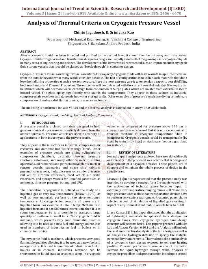
International Journal of Trend in Scientific Research and Development (IJTSRD) Volume: 3 | Issue: 2 | Jan-Feb 2019 Available Online: www.ijtsrd.com e-ISSN: 2456 - 6470 Analysis of Thermal Criteria on Cryogenic Pressure Vessel Chintu Jagadeesh, K. Srinivasa Rao Department of Mechanical Engineering, Sri Vaishnavi College of Engineering, Singupuram, Srikakulam, Andhra Pradesh, India ABSTRACT After a cryogenic liquid has been liquefied and purified to the desired level; it should then be put away and transported. Cryogenic fluid storage-vessel and transfer line design has progressed rapidly as a result of the growing use of cryogenic liquids in many areas of engineering and science. The development of the Dewar vessel represented such an improvement in cryogenic fluid storage vessels that it could be classed as “break-through” in container design. Cryogenic Pressure vessels are weight vessels are utilized for capacity cryogenic fluids with least warmth in-spill into the vessel from the outside beyond what many would consider possible. The test of configuration is to utilize such materials that don't lose their alluring properties at such a low temperature. Here the most extreme care is taken to plan a capacity vessel fulfilling both mechanical and Thermal Properties. The outcomes will be contrasted with the current vessel of industry. Glass epoxy can be utilized which will decrease warm exchange from conduction of Surge plates which are bolster from external vessel to inward vessel. The glass epoxy significantly with stands the temperature. They appear in these sectors as industrial compressed air receivers and domestic hot water storage tanks. Other examples of pressure vessels are diving cylinders, re compression chambers, distillation towers, pressure reactors, etc. The modeling is performed in Catia V5R20 and the thermal analysis is carried out in Ansys 15.0 workbench. KEYWORDS: Cryogenic tank, modeling, Thermal Analysis, Cryogenics I. INTRODUCTION A pressure vessel is a closed container designed to hold gases or liquids at a pressure substantially different from the ambient pressure. Pressure vessels are used in a variety of applications in both industry and the private sector. They appear in these sectors as industrial compressed air receivers and domestic hot water storage tanks. Other examples of pressure vessels are diving cylinders, re compression chambers, distillation towers, pressure reactors, autoclaves, and many other vessels in mining operations, oil refineries and petrochemical plants, nuclear reactor vessels, submarine and space ship habitats, pneumatic reservoirs, hydraulic reservoirs under pressure, rail vehicle airbrake reservoirs, road vehicle air brake reservoirs, and storage vessels for liquefied gases such as ammonia, chlorine, propane, butane, and LPG. The denotation “cryogenics” is defined as the study of a liquefied gas at very low temperature (below−150°C), as well as how materials perform at the aforementioned temperature. At cryogenic temperature all gases are in liquefied form. For example at -162 c temp. Methane is in liquefied form and it has 580 times less volume then it is at room temperature. So it is possible to transport large quantity of methane in small tank. The cryogenic fluid is methane, which presents very good flammable qualities allowing it to be used as a new fuel and energy source. It is used in numbers of industries as fuel in boilers or in chemical industries. The cryogenic fluid is methane, which presents very good flammable qualities allowing it to be used as a new fuel and energy source. It is used in numbers of industries as fuel in boilers or in chemical industries. Methane can be transported in liquid state at cryogenic temp. In cryogenic vessel or in compressed for pressure above 350 bar in convectional pressure vessel. But it is more economical to transfer methane at cryogenic temperature Then in compressed. Cryogenic vessels could be transportable (by road, by train or by boat) or stationary (set on a gas plant, for instance). II. REVIEW OF LITERATURE Journal papers and patents explored here are related directly or indirectly to the proposed area of work that is design and development of a Cryogenic vessel. These papers are to support and enlighten the whole process of design in the specific area. Lisowski [1]in his paper stated that the present study was intended to develop a concept for a Cryogenic vessel, with the motivation of technical gases becomes liquid in extremely low temperature ranging minus 200 °C and very high pressure what makes that transportation devices have to perform very strict requirement. Presented paper shows selected aspect of simulation of liquefied gas sloshing in aspect of requirements that mobile vessels have to fulfill. J. Jaya Kumar, [2] in his paper discussed that the application of lightweight materials in spherical tank designs for cryogenic tanks. Two cryogenic hydrogen tank design concepts will be considered. This paper is prepared with Mat Lab and Abacus Version 6.10.1 and the Analysis will include thermal and structural analysis of the tank designs as well as an analysis of hydrogen diffusion to specify the material permeability requirements. Thermal modeling and analysis of a cryogenic tank design exposed to extreme heating profiles, Thermal performance comparison of insulation systems for liquid hydrogen storage tanks, Analysis of cryogenic propellant tank pressurization based upon ground @ IJTSRD | Unique Reference Paper ID - IJTSRD20307 | Volume – 3 | Issue – 2 | Jan-Feb 2019 Page: 205
International Journal of Trend in Scientific Research and Development (IJTSRD) @ www.ijtsrd.com eISSN: 2456-6470 experiments. A vacuum-jacketed design with an aluminum tank offered the most efficient thermal insulation design option. A tank design with high or low density aero gels results in a much heavier tank system, due to a higher rate of heat penetration and more propellant boil off. As such, aerogels are not a viable insulation option for the storage of cryogenic fuels. SM. Aceves, [3] in his paper described that an analytical and experimental evaluation of the applicability of insulated pressure vessels for hydrogen-fuelled light-duty vehicles. Insulated pressure vessels are cryogenic-capable pressure vessels that can be fuelled with liquid hydrogen(LH?) or ambient-temperature compressed Insulated pressure vessels offer the advantages of liquid hydrogen tanks (low weight and volume), with reduced disadvantages (lower energy requirement for hydrogen liquefaction and reduced evaporative losses). Craig A. Stephens[4] in his study stated that cryogenic test article, the Generic Research Cryogenic Tank, was designed to qualitatively simulate the thermal response of trans- atmospheric vehicle fuel tanks exposed to the environment of hypersonic flight. One-dimensional and two-dimensional finite-difference thermal models were developed to simulate the thermal response and assist in the design of the Generic Research Cryogenic Tank. The one-dimensional thermal analysis determined the required insulation thickness to meet the thermal design criteria and located the purge jacket to eliminate the liquefaction of air. The two-dimensional thermal analysis predicted the temperature gradients developed within the pressure-vessel wall, estimated the cryogen boil off, and showed the effects the ullage condition has on pressure-vessel temperatures. III. MODELING OF CRYOGENIC VESSEL The modeling of a Cryogenic Vessel is done in Catia V5 R20 modeling software. The model of a Cryogenic Vessel is as shown in the Fig. 1. IV. Geometry and Domain are created in ANSYS 15.0. Blocking and Meshing is done. Checking the mesh quality and saving the file to solver Workbench 15.0. Computing and monitoring the solution in solver. Examine and save the results. The analysis of the Cryogenic Pressure Vessel is done in Ansys 15.0 and the analysis reports are as shown below. The geometric model for the Cryogenic vesselStructural steel with Aluminium position is as shown in the Fig. 3 COMPUTATION ANALYSIS hydrogen (CH2). Fig.3 Geometry of the Cryogenic vessel Structural steel with Aluminum position The meshed model for the Cryogenic vessel Structural steel with Aluminium position is as shown in the Fig. 4 Fig.1 Model of a Cryogenic Vessel The drawing specifications of a Cryogenic Vessel are as shown in the Fig. 2. Fig.4. Meshed model of the Cryogenic vessel Structural steel with Aluminium position The analysis is carried out for the Steel material and Different materials are being analyzed for different conditions and materials used are Structural steel, Stainless steel, Aluminium and S- glass epoxy for the outer structure with Aluminium, copper and stainless steel for the inner structure of the Cryogenic Pressure Vessel. The Boundary Conditions are given Temperature of -173 degree C. Convection along with Inner pressure of 0.7 MPa also with Vacuum pressure along the inner and outer tubes. The Deformation for the Cryogenic vessel Structural steel with Aluminum position is as shown in the Fig. 5 Fig.2 Drawing Specifications of a Cryogenic Vessel @ IJTSRD | Unique Reference Paper ID - IJTSRD20307 | Volume – 3 | Issue – 2 | Jan-Feb 2019 Page: 206
International Journal of Trend in Scientific Research and Development (IJTSRD) @ www.ijtsrd.com eISSN: 2456-6470 The Temperature for the Cryogenic vessel Structural steel with Aluminium position is as shown in the Fig. 8 Fig.5 Deformation of the Cryogenic vessel Structural steel with Aluminium position The Equivalent Stress for the Cryogenic vessel Structural steel with Aluminium position is as shown in the Fig. 6 Fig.8 Temperature for the Cryogenic vessel Structural steel with Aluminium position The Total Heat flux for the Cryogenic vessel Structural steel with Aluminium position is as shown in the Fig. 9 Fig.6 Equivalent Stress for the Cryogenic vessel Structural steel with Aluminium position The Equivalent Elastic Strain for the Cryogenic vessel Structural steel with Aluminium position is as shown in the Fig. 7 Fig. 9 Total Heat flux for the Cryogenic vessel Structural steel with Aluminium position Graph for Stress Variations at different liquids: The Graphs for various stress variations at various liquids are as shown in the Graph Fig.7 Equivalent Elastic Strain for the Cryogenic vessel Structural steel with Aluminium position @ IJTSRD | Unique Reference Paper ID - IJTSRD20307 | Volume – 3 | Issue – 2 | Jan-Feb 2019 Page: 207
International Journal of Trend in Scientific Research and Development (IJTSRD) @ www.ijtsrd.com eISSN: 2456-6470 The Graphs for various deformation variations at various liquids are as shown in the Table different temperatures. Taking weight into consideration and stress into account, S- glass epoxy for the outer structure with aluminum for the inner structure is comparably better than the other materials. Future Scope of Work: Different composite materials can be analyzed for various combinations of inner and outer structures. Various angle orientations can be imposed for all the composite materials. Shape optimization can be done for various combinations taking the industrial standards into consideration. REFERENCES [1]E. Lisowski, M. Domagała, “Simulation of liquid dynamics in a cryogenic mobile vessels”, Insitute of Applied Informatics, Cracow University of Technology, al. Jana Pawła 37, 31-864. The Graphs for various heat flux variations at various liquids are as shown in the Table [2]K. J. Jaya Kumar, “Heat Transfer Analysis of Light Weight Cryogenic Tank for Space Vehicles”, Indian Journal of Science and Technology, Vol 8(4), 314-319, February 2015. [3]SM. Aceves, J. Martinez-Frias, Garcia-Villazana, “Evaluation of Insulated Pressure Vessels for Cryogenic Hydrogen Storage”, American Society of Mechanical Engineers International Congress and Exposition Nashville, TN November 14-19, 1999. Mechanical Engineering [4]Craig A. Stephens and Gregory J. Hanna, “Thermal Modeling and Analysis of a Cryogenic Tank Design Exposed to Extreme Heating Profiles”, NASA Contractor Report 186012. V. This project work involves the comparison of material optimization of cryogenic pressure vessel under static loading conditions. The analysis carried out is under static loading condition and also thermal base conditions. Different materials are being analyzed for different conditions and materials used are Structural steel, and S- glass epoxy for the outer structure with aluminum, copper and stainless steel for the inner structure. Static Thermal Analysis done at Pressure vessel by storing Cryogenic Fluids like Methane, Liquid Nitrogen and Helium on basis of Temperature at their Phase Change. Taking different temperatures of respective liquids into consideration, as the temperature is letting down by Kelvin scale, heat flux values seem to be tremendously increasing. So cryogenic vessel is able to withstand at CONCLUSIONS [5]S. M. Aceves, J. Martinez-Frias, “Low Temperature and High Pressure Evaluation of Insulated Pressure Vessels for Cryogenic Hydrogen Storage”, O. Garcia-Villazana FIMEE, Universidad de Guanajuato Salamanca, Gto. Mexico, Jan 2000. [6]A. Hima Bindu, “Design and thermal analysis of cryogenic Fluid storage vessel”, International Journal for Research in Applied Science & Engineering Technology (IJRASET), Special Issue-3, November 2014 [7]Patel PratikKumar BaldevBhai, Prof. Ronak Shah, “Design and Optimization of Cryogenic Storage Vessel”, IJEDR | Volume 3, Issue 1, 2014. [8]https://en.wikipedia.org @ IJTSRD | Unique Reference Paper ID - IJTSRD20307 | Volume – 3 | Issue – 2 | Jan-Feb 2019 Page: 208