Download
1 / 5
50 likes | 55 Views
The increasing population and thus the wide expansion of urban residential areas have increased the need for proper sharing of water. This distribution of water in every house within different areas needs control and monitoring for preventing the wastage of water. Different technologies have been studied to distribute the water to each and every house of residential areas. The main aim of this paper is to provide an effective water supply to each consumer and to detect the leakage sites. Automation provides an optimized solution to all problems of the water distribution system. In order to implement the proposed system, each area must be provided with a water flow sensor which is controlled by the Arduino mega board and can calculate flow rate and the amount of water supplied. The entire system has features of Reliance SCADA Supervisory Control and Data Acquisition to control and monitor the water distribution. In this paper, the system distributes the water under the area of a single water tank. In this way, to control the whole system the automation is developed using PLC Programmable Logic Controller . Khin Nyein Win | Lwin Lwin Htay | Nyan Phyo Aung "Automatic Water Storage and Distribution System using Reliance SCADA" Published in International Journal of Trend in Scientific Research and Development (ijtsrd), ISSN: 2456-6470, Volume-3 | Issue-5 , August 2019, URL: https://www.ijtsrd.com/papers/ijtsrd26414.pdf Paper URL: https://www.ijtsrd.com/engineering/electronics-and-communication-engineering/26414/automatic-water-storage-and-distribution-system-using-reliance-scada/khin-nyein-win<br>

E N D
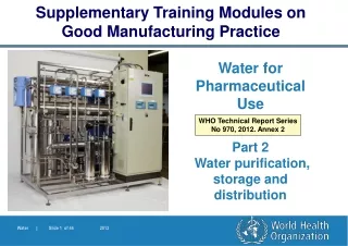
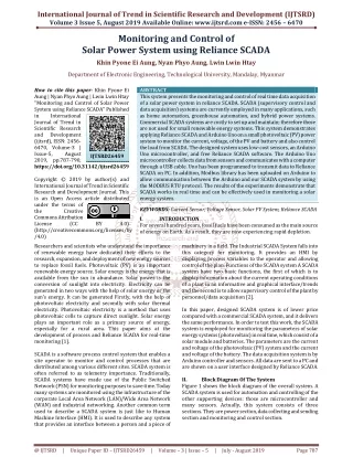
International Journal of Trend in Scientific Research and Development (IJTSRD) Volume 3 Issue 5, August 2019 Available Online: www.ijtsrd.com e-ISSN: 2456 – 6470 Automatic Water Storage and Distribution System using Reliance SCADA Khin Nyein Win, Lwin Lwin Htay, Nyan Phyo Aung Department of Electronic Engineering, Technological University, Mandalay, Myanmar How to cite this paper: Khin Nyein Win | Lwin Lwin Htay | Nyan Phyo Aung "Automatic Water Distribution System using Reliance SCADA" Published in International Journal of Trend in Scientific Research and Development (ijtsrd), ISSN: 2456- 6470, Volume-3 | Issue-5, August 2019, https://doi.org/10.31142/ijtsrd26414 Copyright © 2019 by author(s) and International Journal of Trend in Scientific Research and Development Journal. This is an Open Access article distributed under the terms of the Creative Commons Attribution License (CC (http://creativecommons.org/licenses/by /4.0) In the previous method, the person in charge will go to that place and open the valve for a particular time period. Once the time over again the in charge person will go to the same place and close the valve. It is wastage of time. Also, people may take extra water for their personal use with the help of the motor. The proposed system is fully automated. Here human work and time are reduced. With the rapid development in technology, the more focus is on the selection of application-oriented Controllers and tools, hence the concept of the proposed system to control application it is combined with PLC. Earlier the monitoring of the process was done by human which caused an error. To reduce this error, automation is developed using PLC. [1] The system includes PLC, water flow Sensors, solenoid valve, pump station motor, relay and distribution motor. The PLC monitors the main parameters of the water distribution system. PLC helps in controlling pump station motor, distribution motor, solenoid valves and flow sensor to measure the flow rate of the water. Now-a-days, Water wastage is due to many reasons such as leakage, mankind laziness, operator error etc. Usually, the water pipe is seen leaks, which results in a fountain of burst water. This leakage causes a drastic reduction in the rate of water flowing through the supply line. Due to this, the consumer gets less amount of water. There is also a problem of the irregularity of water supply. Specifically, this research idea focuses on the proper method of water distribution system using PLC and methodology required to protect the leakage of water ABSTRACT The increasing population and thus the wide expansion of urban residential areas have increased the need for proper sharing of water. This distribution of water in every house within different areas needs control and monitoring for preventing the wastage of water. Different technologies have been studied to distribute the water to each and every house of residential areas. The main aim of this paper is to provide an effective water supply to each consumer and to detect the leakage sites. Automation provides an optimized solution to all problems of the water distribution system. In order to implement the proposed system, each area must be provided with a water flow sensor which is controlled by the Arduino mega board and can calculate flow rate and the amount of water supplied. The entire system has features of Reliance SCADA (Supervisory Control and Data Acquisition) to control and monitor the water distribution. In this paper, the system distributes the water under the area of a single water tank. In this way, to control the whole system the automation is developed using PLC (Programmable Logic Controller). KEYWORDS: Flow Sensor; Arduino mega; PLC; Reliance SCADA I. INTRODUCTION Automation plays an increasingly important role in the global economy and in daily experience. It improves the performance and also reduces human efforts hence PLC based water distribution system is implemented. The main objective behind selecting this project is to improve the performance of water distribution system with minimum human efforts. Storage and IJTSRD26414 pp.698-702, BY 4.0) and constant flow rate maintenance while water distribution. [2,3] To overcome this problem an automated system has been proposed which optimizes the water distribution by reducing wastage of water. This system focuses on a control system for controlling and monitoring components within a water distribution system. By considering the above scenario we are trying to find a solution to the problem. The water supply system is a part of the urban need which must assure the continuityof the water distribution. The PLC receives information from level sensors and flow sensors and sends the signal to the water pump motor, distribution motor and valves. PLC takes the output from these sensors and values are displayed on Computer. [4] II. LITERATURE SURVEY Initially, we studied the working of the distribution system of the existing system. For this project, we have taken the reference of paper, “Automated Drinking Water Distribution Using Arduino (International Journal of Electrical and Electronics Engineers, IJEEE, Volume 07, Issue 01, Jan-June 2015)” and “An Embedded Based Monitoring and Distribution System for Water Supply in Urban Area (International Journal of Engineering Science and Computing, May 2017)”. Also, we studied “Survey of SCADA systems and Visualization of a real life process” and “Automation Manufacturing Systems with PLCs”. @ IJTSRD | Unique Paper ID – IJTSRD26414 | Volume – 3 | Issue – 5 | July - August 2019 Page 698
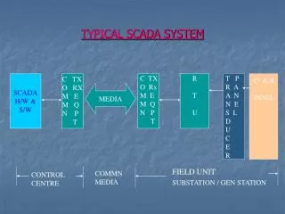
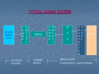
International Journal of Trend in Scientific Research and Development (IJTSRD) @ www.ijtsrd.com eISSN: 2456-6470 III. The Figure 1 shows the block diagram of the proposed system of Water Distribution System Using Reliance SCADA. It consists of the following module such as PLC controller, Sensors such as Flow sensors and water level sensors, actuators such as Solenoid valves and motors. BLOCK DIAGRAM OF SYSTEM DESIGN C.Water Level Sensor Liquid level sensors are used to detect liquid levels or interfaces between liquids such as oil and water or liquids and solids. They can be defined as sensors or transducers, or as integrated systems with instrumentation and control capabilities. A water level sensor is used in this system, in order to indicate the amount of water that is present in the storage tank. D. Flow Sensor A flow sensor is a device for sensing the rate of fluid flow. Typically, a flow sensor is the sensing element used in a flow meter, or logger, to record the flow of fluids. A flow sensor is used in this system, in order to measure the flow rate of water that is entering into each area. Figure 3 shows the Hall Effect flow sensor which used in this system. Figure1: The Block Diagram of System Design A.PLC (Programmable Logic Controller) PLC is a solid-state device which controls its output on the basis of its input and predefined program. A Programmable Logic Controller is a specialized computer used to control machines and processes. It uses a programmable memory to store instructions and execute specific functions that include on/off control, timing, counting, sequencing, arithmetic, and data handling. Basically, the PLC is an assembly of solid-state digital logic elements designed to make logical decisions and provides outputs. Initially, the PLC was used to replace relay logic, but its ever-increasing range of functions means that it is found in many and more complex applications. PLC is a perfect solution for controlling a wide variety of applications. PLC programming is done using Ladder Diagram Language. It is the main schematic language commonly used in automation industrial control logic systems. This system is used SIEMENS PLC S7-1200. Figure 3: Hall Effect Flow Sensor E.Solenoid Valve A solenoid valve is an electromechanically operated valve. The valve is controlled by an electric current through a solenoid: in the case of a two-port valve the flow is switched on or off; in the case of a three-port valve, the outflow is switched between the two outlet ports. A solenoid valve is used in this system, in order to control the flow of water that is entering into the area from the storage tank. The solenoid valve is operated by a PLC controller depending on the predefined program. The solenoid valve is shown in Figure 4. Figure4: Solenoid Valve Figure2: SIEMENS PLC S7-1200 [5] F.Pump (or) Motor A pump is a device that moves fluids (liquids or gases), or sometimes slurries, by mechanical action. Pumps operate by some mechanism (typically reciprocating or rotary), and consume energy to perform mechanical work by moving the fluid. Pumps operate via many energy sources, including manual operation, electricity, engines or wind power, come in many sizes, from microscopic for use in medical applications to large industrial pumps. A pump is used in this system, in order to move the water that is present in the underground tank to the storage tank and to distribute the water into the areas. B.Reliance SCADA The SCADA is the interface through which the user interacts with the system. The current status of the system is communicated to the user. The user can also turn ON or OFF various functions from the interface. SCADA is a system for remote monitoring and control that operates with coded signals over communication channels. The control system may be combined with a data acquisition system by adding the use of coded signals over communication channels to acquire information about the status of the remote equipment for display or for recording functions. [6] @ IJTSRD | Unique Paper ID – IJTSRD26414 | Volume – 3 | Issue – 5 | July - August 2019 Page 699
International Journal of Trend in Scientific Research and Development (IJTSRD) @ www.ijtsrd.com eISSN: 2456-6470 G.Relay A relay is an electrically operated switch. The relay considered in this system uses an electromagnet to operate a switching mechanism mechanically. Any compatible relay can be used with this system. The relay converts the DC output of the PLC into a signal compatible to effectively control motors and valves being used. H.Arduino Mega The mega2560 is a microcontroller board based on ATmega2560 which is chosen as a CPU instead of Arduino UNO to meet the requirements of the proposed system. It consists of 54 digital input and output pins in which (15 can be used for pulse width modulation output) 16 analog input pins, 4 UART’S, 16MHZ crystal oscillator, USB connection, power jack, an In-Circuit Serial Programming header and reset button are present. status of the water level sensor to operate the pump. If the water level reaches a defined level in the storage tank, the pump will be turned off with the help of PLC. The water is flowing through the distribution motor when the main solenoid valve opens. The setpoint is fixed for the solenoid valve. If anyone of its valve or both the valve attains the set point the solenoid valve is turned off. The water entering into the areas are measured through flow sensors in order to monitor the flow rate of water. The PLC controller takes the status of the Flow sensor and controls this by a solenoid valve. The solenoid valve is operated by a PLC in order to stop the water flow or to allow the water flow into the area depending on the predefined program i.e. whenever there is a leakage problem or when repair work is going on. Hence each area is fitted with a one solenoid valve to control the water flowing into the area and a flow sensor in order to monitor the water flowing into the area. The water storage system consists of one storage tank consisting of level sensors and pump. The distribution network consists of the pipeline for water flow, the valve in order to open and close, flow sensors for a flow rate of water and motor for distribution of water. V. SOFTWARE IMPLEMENTATION Figure 5: Arduino Mega IV. THE PROPOSED SYSTEM Figure6: The Proposed System Figure 6 shows the architecture of the proposed system of Water Storage and Distribution system using PLC (Programmable Logic Controller). implementation of the project. This proposed advanced system is three-layer architecture which not only monitors and control water distribution but also finds out water leakage and takes preventive and corrective action to obtain the proper distribution of water. The overall distribution process is monitored in the PC. This system mainly consists of PLC which is the central and important part of the system. The water which is present in the underground tank is moved to the storage tank by the pump if the water in the storage tank is reduced below the predefined level. Hence the PLC controller monitors the It shows the Figure7: Flow Chart of the System Flow chart describes the working of the system. This also indicates the working of the control valve and the timing of the opening and closing of the control valve. The control valve is operated by observing the condition of flow rate and time. When the system is started, the water level in the storage tank is checked. After that, the distribution motor is on. And @ IJTSRD | Unique Paper ID – IJTSRD26414 | Volume – 3 | Issue – 5 | July - August 2019 Page 700
International Journal of Trend in Scientific Research and Development (IJTSRD) @ www.ijtsrd.com eISSN: 2456-6470 then the valves open, and the flow rate is measured. The flow rate of the distribution area is compared with their set value and from that error is detected. If any error is present, then the operator is stopped. The flow chart of the working system is programmed by using Ladder diagram. The ladder program for Siemens S7- 1200 was done in Siemens TIA Portal. VI. EXPERIMENTAL RESULTS Hardware implementation is as shown in figure 8 and 9. This system consists of one storage tank, piping distribution network, PLC interfaced with PC unit. The system gives results for the normal water contents. The valve opens if and only if the water contents are within the normal range. If the water has acidic contents, then valve immediately closed and distribution of water stop. This system also gives the result to identify the excessive flow of water. If actual water flow is different from set flow, this can be observed through the flow sensor. functionality of each code block is tested after its development. Figure10: Program Result of the System The computer is interfaced with a PLC panel as shown in Figure 11. It displays all the information of level and flow rate. Figure8. Water Storage and Distribution Operation Figure11: Monitoring for Water Storage and Distribution Process CONCLUSION This paper discussed here is PLC controlled water distribution system. The conventional method used before in older times, results in problems like empty running, overflow, leakage. The automation of the process thus helped to overcome these problems based on level, flow parameters and it also minimized human efforts for the same. The automation of the water distribution system also eliminates water wastage. SCADA displays it possible to monitor and control the water from the control room. The control room can monitor the system all the time without manpower. The automation system provides continuous water distribution according to water level. This system is excellent and cost-effective. It is the best way to prevent water from wastage. Acknowledgment This work is done with my supervisor, Dr. Lwin Lwin Htay Department of Electronic Engineering, Technological University (Mandalay). The author would like to thank Dr. Nyan Phyo Aung Department of Electronic Engineering, Technological University (Mandalay) for kindly preparing for this paper. VII. Figure9. Hardware Implementation of Water Storage and Distribution System Figure 10 shows the ladder diagram for the main organization block. It consists of three types of functions. Input function, output function and logic function these three functions are like a subroutine. Input and Output are used to read and write the input and output status according to the process change. This process status is passed to logic functions and corrective actions are takes place. As the modular structure is used for programming it is easy to update, modification of program code is easier and quicker. It provides standardize design, therefore, the design of the program can be easier to understand and monitor. The @ IJTSRD | Unique Paper ID – IJTSRD26414 | Volume – 3 | Issue – 5 | July - August 2019 Page 701
International Journal of Trend in Scientific Research and Development (IJTSRD) @ www.ijtsrd.com eISSN: 2456-6470 [6]JOSE ANGEL GOMEZ GOMEZ, June 2000, “Survey of SCADA systems and Visualization of a real life process”, Sweden. References [1]S. Gropalakrishnan and V. Hemalatha “An Embedded Based Monitoring and Distribution System for Water Supply in Urban Areas”, International Journal of Engineering Science and Computing, Vol. 7, Issue 5, May 2017. [7]Nivetha M and Sundaresan S, “Automated Drinking Water Distribution Using Arduino”, SSRG International Journal of Civil Engineering (SSRG-IJCE)-volume 4 Issue 5, May 2017. [2]N. B. Bhawarkar, D. P. Pande, R. S. Sonone and Mohd. Aaquib,“Literature Review for Automated Water Supply with Monitoring the Performance System”, International Journal of Current Engineering and Technology, Vol-4, No.5 Oct 2014. [8]Harish KM, Chaitra R, Divya KS, and Nandini M, “Centralised Water Distribution Monitoring and Controlling System Using PLC and SCADA”, IJSETR Volume 5, Issue 6, June 2016. [3]Sujeet Rote, Adarsh M ourya, Tanmay Oak and Prof. Abhimanyu Yadav “Automation Water Supply System and Water Theft Identification Using PLC and SCADA”, International Journal of Engineering Research & Applications, Vol. 4 Issue 04, April-2014. [9]Rishabh Das, Sayantan Dutta, Anusree Sarkar and Kaushik Samanta, “Automation of Tank Level Using PLC and Establishment of HMI by SCADA”, IOSR Journal of Electrical and Electronics Engineering, Volume 7, Issue 2, July-Aug. 2013. [4]Ramleela Khare and Dr. Filipe Rodrigues E Melo, “Automation of Water Distribution Plant”, IJREAT International Journal of Research in Engineering & Advanced Technology, Volume 2, Issue 1, Feb-Mar, 2014. [10]GEOVAP, “Reliance 4 Building Automation”, @ 2018, spol. sr. o. [11]Siemens, “S7-1200 Programmable Controller”, System Manual, 01/2015, A5E02486680-AH, Copyright © Siemens AG 2015. [5]Hug Jack, April 14, 2005, “Automation Manufacturing Systems with PLCs”, Version 4.7, Person Education (Singapore). @ IJTSRD | Unique Paper ID – IJTSRD26414 | Volume – 3 | Issue – 5 | July - August 2019 Page 702