Download
1 / 17
170 likes | 174 Views
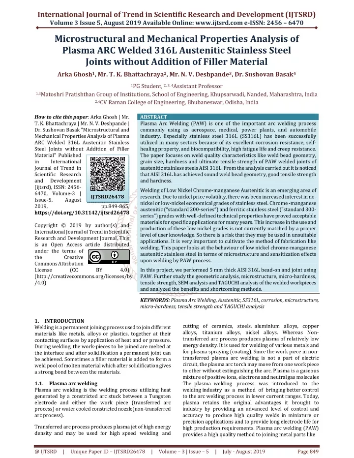
Plasma Arc Welding PAW is one of the important arc welding process commonly using as aerospace, medical, power plants, and automobile industry. Especially stainless steel 316L SS316L has been successfully utilized in many sectors because of its excellent corrosion resistance, self healing property, and biocompatibility, high fatigue life and creep resistance. The paper focuses on weld quality characteristics like weld bead geometry, grain size, hardness and ultimate tensile strength of PAW welded joints of austenitic stainless steels AISI 316L. From the analysis carried out it is noticed that AISI 316L has achieved sound weld bead geometry, good tensile strength and hardness. Welding of Low Nickel Chrome manganese Austenitic is an emerging area of research. Due to nickel price volatility, there was been increased interest in no nickel or low nickel economical grades of stainless steel. Chrome manganese austenitic "standard 200 series"u009d and ferritic stainless steel "standard 300 series"u009d grades with well defined technical properties have proved acceptable materials for specific applications for many years. This increase in the use and production of these low nickel grades is not currently matched by a proper level of user knowledge. So there is a risk that they may be used in unsuitable applications. It is very important to cultivate the method of fabrication like welding. This paper looks at the behaviour of low nickel chrome manganese austenitic stainless steel in terms of microstructure and sensitization effects upon welding by PAW process. In this project, we performed 5 mm thick AISI 316L bead on and joint using PAW. Further study the geometric analysis, microstructure, micro hardness, tensile strength, SEM analysis and TAGUCHI analysis of the welded workpieces and analyzed the benefits and shortcoming methods. Arka Ghosh | Mr. T. K. Bhattachraya | Mr. N. V. Deshpande | Dr. Sushovan Basak "Microstructural and Mechanical Properties Analysis of Plasma ARC Welded 316L Austenitic Stainless Steel Joints without Addition of Filler Material" Published in International Journal of Trend in Scientific Research and Development (ijtsrd), ISSN: 2456-6470, Volume-3 | Issue-5 , August 2019, URL: https://www.ijtsrd.com/papers/ijtsrd26478.pdf Paper URL: https://www.ijtsrd.com/engineering/mechanical-engineering/26478/microstructural-and-mechanical-properties-analysis-of-plasma-arc-welded-316l-austenitic-stainless-steel-joints-without-addition-of-filler-material/arka-ghosh<br>

E N D
International Journal of Trend in Scientific Research and Development (IJTSRD) Volume 3 Issue 5, August 2019 Available Online: www.ijtsrd.com e-ISSN: 2456 – 6470 Microstructural and Mechanical Properties Analysis of Plasma ARC Welded 316L Austenitic Stainless Steel Joints without Addition of Filler Material Arka Ghosh1, Mr. T. K. Bhattachraya2, Mr. N. V. Deshpande3, Dr. Sushovan Basak4 1PG Student, 2, 3, 4Assistant Professor 1,3Matoshri Pratishthan Group of Institutions, School of Engineering, Khupsarwadi, Nanded, Maharashtra, India 2,4CV Raman College of Engineering, Bhubaneswar, Odisha, India How to cite this paper: Arka Ghosh | Mr. T. K. Bhattachraya | Mr. N. V. Deshpande | Dr. Sushovan Basak "Microstructural and Mechanical Properties Analysis of Plasma ARC Welded 316L Austenitic Stainless Steel Joints without Addition of Filler Material" Published in International Journal of Trend in Scientific Research and Development (ijtsrd), ISSN: 2456- 6470, Volume-3 | Issue-5, August 2019, pp.849-865, https://doi.org/10.31142/ijtsrd26478 Copyright © 2019 by author(s) and International Journal of Trend in Scientific Research and Development Journal. This is an Open Access article distributed under the terms of the Creative Commons Attribution License (CC BY 4.0) (http://creativecommons.org/licenses/by /4.0) 1.INTRODUCTION Welding is a permanent joining process used to join different materials like metals, alloys or plastics, together at their contacting surfaces by application of heat and or pressure. During welding, the work-pieces to be joined are melted at the interface and after solidification a permanent joint can be achieved. Sometimes a filler material is added to form a weld pool of molten material which after solidification gives a strong bond between the materials. 1.1. Plasma arc welding Plasma arc welding is the welding process utilizing heat generated by a constricted arc stuck between a Tungsten electrode and either the work piece (transferred arc process) or water cooled constricted nozzle(non-transferred arc process). Transferred arc process produces plasma jet of high energy density and may be used for high speed welding and ABSTRACT Plasma Arc Welding (PAW) is one of the important arc welding process commonly using as aerospace, medical, power plants, and automobile industry. Especially stainless steel 316L (SS316L) has been successfully utilized in many sectors because of its excellent corrosion resistance, self- healing property, and biocompatibility, high fatigue life and creep resistance. The paper focuses on weld quality characteristics like weld bead geometry, grain size, hardness and ultimate tensile strength of PAW welded joints of austenitic stainless steels AISI 316L. From the analysis carried out it is noticed that AISI 316L has achieved sound weld bead geometry, good tensile strength and hardness. Welding of Low Nickel Chrome-manganese Austenitic is an emerging area of research. Due to nickel price volatility, there was been increased interest in no- nickel or low-nickel economical grades of stainless steel. Chrome -manganese austenitic (“standard 200-series”) and ferritic stainless steel (“standard 300- series”) grades with well-defined technical properties have proved acceptable materials for specific applications for many years. This increase in the use and production of these low nickel grades is not currently matched by a proper level of user knowledge. So there is a risk that they may be used in unsuitable applications. It is very important to cultivate the method of fabrication like welding. This paper looks at the behaviour of low nickel chrome-manganese austenitic stainless steel in terms of microstructure and sensitization effects upon welding by PAW process. In this project, we performed 5 mm thick AISI 316L bead-on and joint using PAW. Further study the geometric analysis, microstructure, micro-hardness, tensile strength, SEM analysis and TAGUCHI analysis of the welded workpieces and analyzed the benefits and shortcoming methods. KEYWORDS: Plasma Arc Welding, Austenitic, SS316L, corrosion, microstructure, micro-hardness, tensile strength and TAGUCHI analysis IJTSRD26478 cutting of ceramics, steels, aluminium alloys, copper alloys, titanium alloys, nickel alloys. Whereas Non- transferred arc process produces plasma of relatively low energy density. It is used for welding of various metals and for plasma spraying (coating). Since the work piece in non- transferred plasma arc welding is not a part of electric circuit, the plasma arc torch may move from one work piece to other without extinguishing the arc. Plasma is a gaseous mixture of positive ions, electrons and neutral gas molecules The plasma welding process was introduced to the welding industry as a method of bringing better control to the arc welding process in lower current ranges. Today, plasma retains the original advantages it brought to industry by providing an advanced level of control and accuracy to produce high quality welds in miniature or precision applications and to provide long electrode life for high production requirements. Plasma arc welding (PAW) provides a high quality method to joining metal parts like @ IJTSRD | Unique Paper ID – IJTSRD26478 | Volume – 3 | Issue – 5 | July - August 2019 Page 849
International Journal of Trend in Scientific Research and Development (IJTSRD) @ www.ijtsrd.com eISSN: 2456-6470 A.Speed of operation and low distortion. B.Reduces post-weld straightening operations. C.Low build up reduces polishing and grinding procedures. d. Weld metal integrity- keyhole fuses parent metal. D.High-quality weld integrity and appearance. E.Reduction in the preparation times for assemblies by eliminating bevelling for F.thicknesses up to 8 mm (5/16”). G.Reduction in welding time in comparison to manual welding. H.Assurance of complete and regular penetration by virtue of the keyhole technique on butt joints. Plasma arc welding is advancement over the GTAW process. This process uses a non- consumable tungsten electrode and an arc constricted through a fine-bore copper nozzle. PAW can be used to join all metals that are weld able with GTAW (i.e., most commercial metals and alloys). Difficult-to-weld in metals by PAW include bronze, cast iron, lead and magnesium. Several basic PAW process variations are possible by varying the current, plasma gas flow rate, and the orifice diameter, including: Plasma arc welding process uses plasma to transfer an electric arc to a work piece. The metal to be welded is melted by the intense heat of the arc and fuses together. In the plasma welding torch a Tungsten electrode is located within a copper nozzle having a small opening at the tip Micro-plasma (< 15 Amperes) Melt-in mode (15–100 Amperes) Keyhole mode (>100 Amperes) Plasma arc welding has a greater energy concentration as compared to GTAW. A deep, narrow penetration is achievable, with a maximum depth of 12 to 18 mm (0.47 to 0.71 in) depending on the material. Greater arc stability allows a much longer arc length (stand-off), and much greater tolerance to arc length changes. PAW requires relatively expensive and complex equipment as compared to GTAW; proper torch maintenance is critical Welding procedures tend to be more complex and less tolerant to variations in fit -up, etc. Operator skill required is slightly greater than for GTAW. Orifice replacement is necessary. PLASMA ARC (150A-28V) It diverges very little outside of the nozzle which is cooled. The 10,000-16,000oC temperature zone is transferred to the part in a concentrated beam. Fig: 1.1: Plasma Arc Welding Process 1.1.1.How Plasma Formed The plasma is generated by constricting the electric arc passing through the orifice of the nozzle. Hot ionized gases are also forced through this opening. The plasma has a stiff columnar form and is parallel sided so that it does not flare out in the same manner as the gas tungsten arc. This high temperature arc, when directed toward the work, will melt the base metal surface and the filler metal that is added to make the weld. In this way, the plasma acts as an extremely high temperature heat source to form a molten weld puddle. This is similar to the gas tungsten arc. The higher-temperature plasma, however, causes this to happen faster, and is known as the melt-in mode of operation. Fig 1.2: Plasma arc @ IJTSRD | Unique Paper ID – IJTSRD26478 | Volume – 3 | Issue – 5 | July - August 2019 Page 850
International Journal of Trend in Scientific Research and Development (IJTSRD) @ www.ijtsrd.com eISSN: 2456-6470 The high temperature of the plasma or constricted arc and the high velocity plasma jet provide an increased heat transfer rate over gas tungsten arc welding when using the same current. This results in faster welding speeds and deeper weld penetration. This method of operation is used for welding extremely thin material and for welding multi- pass groove and welds and fillet welds. In automatic plasma complete penetration of material up to 8 mm (5/16”) thick is possible on square edge butt joints. Productivity is improved as well, due to simplification of preparation. 1.1.2.Plasma Arc Welding Process Technique of work piece cleaning and filler metal addition is similar to that in TIG welding. Filler metal is added at the leading edge of the weld pool. Filler metal is not required in making root pass weld. 1.1.2.1. Type of Joints: For welding work piece up to 25 mm thick, joints like square butt, J or V are employed. Plasma welding is used to make both key hole and non-keyhole types of welds. 1.1.2.2.Making a non-keyhole weld: The process can make non keyhole welds on work pieces having thickness 2.4 mm and under. 1.1.2.3.Making a keyhole welds: An outstanding characteristic of plasma arc welding, owing to exceptional penetrating power of plasma jet, is its ability to produce keyhole welds in work piece having thickness from 2.5 mm to 25 mm [31]. A keyhole effect is achieved through right selection of current, nozzle orifice diameter and travel speed, which create a forceful plasma jet to penetrate completely through the work piece. Plasma jet in no case should expel the molten metal from the joint. The major advantages of keyhole technique are the ability to penetrate rapidly through relatively thick root sections and to produce a uniform under bead without mechanical backing. Also, the ratio of the depth of penetration to the width of the weld is much higher, resulting narrower weld and heat -affected zone. As the weld progresses, base metal ahead the keyhole melts, flow around the same solidifies and forms the weld bead. Key holing aids deep penetration at faster speeds and produces high quality bead. While welding thicker pieces, in laying others than root run, and using filler metal, the force of plasma jet is reduced by suitably controlling the amount of orifice gas. Fig: 1.3: Displacement of Keyhole Positions Fig: 1.4 Geometrical Parameters of the Keyhole Table1.1: Different type of Plasma gases for different Steel PLASMA TIG+PLASMA TIG Table for Choice of gases: ANNULAR OR SHIELDING GAS Argon+H2 Argon+H2 Argon+CO2 PLASMA GAS BACKING GAS GAS Argon Argon+H2 Argon+H2 Argon Argon CARBON AND LOW ALLOYED STEELS Argon+H2 Nitrogen Nitrogen+H2 Argon Argon+H2 Argon Argon+H2 Argon + He Argon+H2 Argon Argon AUSTENITIC STAINLESS STEELS Argon+H2 Argon+H2 Argon+H2 Argon Argon+H2 Argon Argon+H2 Argon Argon Argon+H2 Argon Argon + He Argon + He Argon Argon + He He NICKEL- BASED PRECIOUS METALS (titanium, tantalum, zirconium) Argon Argon Argon + He Argon ALUMINUM & ALLOYS Argon Argon Argon + He @ IJTSRD | Unique Paper ID – IJTSRD26478 | Volume – 3 | Issue – 5 | July - August 2019 Page 851
International Journal of Trend in Scientific Research and Development (IJTSRD) @ www.ijtsrd.com eISSN: 2456-6470 5.A wide range of metal can be welded. Nonferrous metals like aluminium, copper and dissimilar metal can be welded. 1.4.Plasma assisted TIG welding Plasma welding is similar to TIG welding. The difference is that in plasma welding, the arc is sharply constricted by a cooled gas nozzle through which a flow of plasma gas is directed. The shielding gas flows through the outside gas nozzle, providing an optimum gas shield to the weld seam. The concentrated arc results in maximum energy focus, leading to a deep penetration effect in the work piece that can only be matched by a laser beam. What is more, the welding speed is as much as 20% faster than in mechanized TIG welding. The use of plasma and TIG welding in tandem produces deep penetration from the plasma lead torch and increased speed and appearance due to the trailing TIG torch. This process is mainly used in sheet-metal work for long-length welds. For the plasma + TIG process, a TIG torch, as well as a cold wire feeder, is positioned approximately 160 mm behind the plasma torch. The plasma arc ensures the penetration of the entire thickness of the joint, while the TIG torch, complete with magnetic oscillation and a cold wire feeder, produces a simultaneous finishing pass. This configuration increases the speed by 30 % in relation to single-torch plasma. Plasma assisted TIG welding process is generally applicable to welds with a length > 3,000 mm (10”), or with parts with diameters greater than 2,200 mm(7”). The Plasma assisted TIG welding (bi-cathode) has significant advantages: ?Single-pass operation, ?Reduction in the quantity of filler metal used, ?High-speed welding, ?Low deformation, ?Narrowness of the heat-affected area, ?High-quality X Ray, ?Reduced thickness, very nice appearance of the weld bead, reducing grinding and polishing times. 1.2.Working Principle of PAW: This welding works on same as TIG instead, plasma is used to heat up the parent material. Its working can be summarized as follow. First the work pieces are properly cleaned. The power source supply power which produces arc between tungsten electrode and nozzle, or tungsten electrode and work piece. The tungsten electrode gives a high intense arc which is used to ionization of gas particles and converts orifice gases into plasma. This hot ionized gas is supplied to the welding plates from a small orifice. The shielding gases like argon etc are supplied through pressure valve and regulating valve to the outer nozzle of welding torch. These gases create a shield around the welding area which protect it from atmospheric gases like oxygen, nitrogen etc. The plasma strikes the welding plates and fuses it into one piece. Next the welding torch is moved in the direction of welding. If the welding required filler material, it is fed by the welder manually. 1.2.1.Advantages ?High welding speed. ?High energy available for welding. It can be easily used to weld hard and thick work pieces. ?The distance between tool and work piece does not effects the arc formation. ?Low power consumption for same size weld. ?More stable arc produced by PAW method. ?High intense arc or high penetration rate. ?It can work at low amperage. 1.2.2.Disadvantages ?Higher equipment cost. ?More radiation. ?High skill labor required. ?High maintenance cost. 1.3.Gas Tungsten Arc Welding (GTAW) or Tungsten Inert Gas (TIG): GTAW or TIG welding process is an arc welding process uses a non-consumable tungsten electrode to produce the weld. The weld area is protected from atmosphere with a shielding gas generally, Argon or Helium or sometimes mixture of Argon and Helium. A filler metal may also feed manually for proper welding. GTAW most commonly called TIG welding process was developed during Second World War. With the development of TIG welding process, welding of difficult to weld materials e.g. Aluminum and Magnesium become possible. The use of TIG today has spread to a variety of metals like stainless steel, mild steel and high tensile steels, Al alloy, Titanium alloy. Like other welding system, TIG welding power sources have also improved from basic transformer types to the highly electronic controlled power source today. 1.No flux is required because inert gas shields molten metal. So no slag and slag inclusion problems. 2.High quality and Strong welding achieved by TIG. 3.Non- Corrosive and ductile joints. 4.It can be done in both automatic and manual. Fig 1.5: Graph of Speed vs. Thickness plasma + TIG @ IJTSRD | Unique Paper ID – IJTSRD26478 | Volume – 3 | Issue – 5 | July - August 2019 Page 852
International Journal of Trend in Scientific Research and Development (IJTSRD) @ www.ijtsrd.com eISSN: 2456-6470 Table 1.2: Comparison of Welding Speeds of Plasma & Plasma+TIG [Broacher, “TIG and Plasma process”, www.airliquide.ca, Air Liquide] THICKNESS PLASMA mm(in) Welding Speed cm/min(in/min) 3 (0.12) 50 (19) 4 (5/32) 35-40 (14-16) 50-60 (20-24) 5 (0.2) 25-30 (10-12) 8 (5/16) 15-20 (6-8) 1.5.2.Type of L L" stands for 'low carbon' 304L Alloy 304L a 300 series stainless steel austenitic, which has a minimum of 18% chromium and 8% nickel. 308L Grade 308L stainless steel is a low carbon version of grade 308. 316L The main difference is the lower carbon content, 316 being 0.030, 316L being as low as 0.016. The 316L is more ductile when annealed. It is more resistant to general corrosion and pitting than conventional nickel chromium stainless steels such as 302- 304. Alloy 316L Alloy 316/316L (UNSS31600/S31603) is chromium- nickel-molybdenum austenitic stainless steel developed to provide improved corrosion resistance to Alloy 304/304L in moderately corrosive environments. In most applications Alloy 316/316L has superior corrosion resistance to Alloy 304/304L.Alloy 316/316L can be easily welded and processed by standard shop fabrication practices. 316L austenitic stainless steel alloy wrought plates with mentions of 150 mm 9 150 mm 9 9 mm were selected for the welding experiments, with the average composition of 0.025%C, 48%Si, 1.26%Mn, 10.2%Ni, 17.7%Cr, 0.032%P, 0.002%S, 0.0021%O and the rest of Fe. A post weld heat treatment is not necessary. Table1.3: Chemical composition of different grade of SS Element Type 316 (%) Carbon 0.08 max. Manganese 2.00 max. Phosphorus 0.045 max. Sulfur 0.03 max. Silicon 0.75 max. Chromium 16.00-18.00 Nickel 10.00-14.00 Molybdenum 2.00-3.00 Nitrogen 0.10 max. Iron Balance 1.5.3.Application: 1.Using plasma+TIG processes for flat position, or circular welding of stainless steel, noble metals, steels or aluminium. Manufacture all types of products for the petrochemical, agriculture/food aeronautical industries, etc. 2.Using plasma+TIG processes for horizontal welding of stainless steel, noble metals, steels or aluminium. Manufacture storage equipment for agriculture/food processing, petrochemical industries, etc. PLASMA+TIG 65 (26) 40 (16) 25 (10) 1.High quality of plasma weld. 2.30 to 50 % increase in productivity. 3.Can be adapted to varied boiler-making processes due to its great flexibility. 4.No weld-seam preparation 5.Filler metal and higher availability of the wearing parts 6.In order for plasma to form, very high temperatures of up to 25,000 °C are needed. The concentrated arc, however, the heat input is so precisely targeted that considerably less component distortion occurs than in TIG welding. The plasma + TIG process is specially designed for large capacity stainless steel boiler work: length > 3 meters, - diameter > 2.2 meters, or manufacture of large stainless steel tubes welded in one piece. 1.5.Austenitic stainless steel Austenitic steels are non-magnetic stainless steels that contain high levels of chromium and nickel and low levels of carbon. Known for their formability and resistance to corrosion, austenitic steels are the most widely used grade of stainless steel. There are many types of Austenitic Stainless Steel. They are 200 Series, 300 Series, and 400 Series. But nowadays 300 Series Austenitic Stainless Steel are use because these Stainless steel alloys resist corrosion, maintain their strength at high temperatures and are easy to maintain. They most commonly include chromium, nickel and molybdenum. Stainless steel alloys are used predominantly in the automotive, construction industries. Austenitic stainless steels are used in a wide range of applications, including automotive trim, cookware, beverage and chemical equipment, industrial equipment and pipeline grade. 1.5.1.Nickel-based austenitic steels are classified as 300 series: 304 Stainless Steel: This non-magnetic alloy is the most versatile and the most widely used of all stainless steels. 308 Stainless Steel typically contains about 20 % chromium and an average of 11 % nickel. 316 Stainless Steel: This alloy is recommended for welding because it has a carbon content lower than 302 to avoid carbide precipitation in welding applications. The addition of molybdenum and a slightly higher nickel content make 316 Stainless Steel suitable for architectural applications in severe settings, from polluted marine environments to areas with sub-zero temperatures. Equipment in the chemical, food, paper, mining, and pharmaceutical and petroleum industries often includes 316 Stainless Steel. Type 316L (%) 0.03 max. 2.00 max. 0.045 max. 0.03 max. 0.75 max. 16.00-18.00 10.00-14.00 2.00-3.00 0.10 max. Balance aerospace and processing, @ IJTSRD | Unique Paper ID – IJTSRD26478 | Volume – 3 | Issue – 5 | July - August 2019 Page 853
International Journal of Trend in Scientific Research and Development (IJTSRD) @ www.ijtsrd.com eISSN: 2456-6470 Kunio Narita [2] investigated the effect of different welding parameters of plasma arc welding process on the shape of welds and consistency of defects in the flat, vertical and overhead positions of mild steel pipes of thickness 6.4mm and outer diameter 406.4mm. Katsunori Inoue et.al [3] presented the method of measurement for the penetration and the control circuit which adjusts adaptively the pulsed current duration depending on the results of penetration quality with on-line measurement. Welding experiment and theoretical analysis indicate that the system can ensure uniform penetration quality under the disturbing condition. T. Ishida [4] investigated the interfacial microstructures and intermetallic compounds produced by plasma arc butt fusion welding of aluminium to mild steel. Experiments were carried out on 5mm thick mild steel and aluminium plates. An intermetallic co mpound alloy layer formed at the interface region between mild steel and aluminium was determined using quantitative metallography and the mechanism of the intermetallic layer formation and growth was elucidated. Russell G. Keanini [5-6] presented a three dimensional finite element model of the plasma arc welding process. The model allows calculation of the weld pools approximate capillary and solid-liquid phase boundaries; the weld pools three dimensional flow and temperature fields and solid phase temperature distribution. The results reveal that flow in vertical cross sections is dominated by a large jet driven vortex, competition between surface tension and jet shear produces a stagnation region near the top of the pool, flow in horizontal planes are largely determined by the plate‟s motion and buoyancy is a secondary driving force within the plasma arc weld pool. D. K. Zhang et.al [7] studied the influence of welding current, arc voltage, welding speed, wire feed rate and magnitude of ion gas flow on front melting width, back melting width and weld reinforcement of Alternating Current Plasma Arc Welding process using Artificial Neural Network- Back Propagation algorithm. He used LF6 aluminium alloy of size 300 x 80 x 3mm. Orthogonal sing design matrix was used to perform the experiments. G. Ravichandran [8] carried out thermal analysis of molten pool formation and solidification for keyhole welding using Plasma Arc Welding has been done using Finite Element Method. Yaowen Wang et.al [9] addressed the problems involved in the automatic monitoring of the weld quality produced by plasma arc keyhole welding. The acoustic signal of plasma arc welding was acquired by using a condenser microphone at high speed and analyzed with the aid of computers. It is shown that the overall AC power of the acoustic analysis, especially the low frequency part (0±100 Hz) of the acoustic signal power spectra, greatly varies with the variation of the statuses of the weld pool. Yaowen Wang et.al [10] acquired weld voltage and current simultaneously at high speed and investigated with the aid of computers and reported that the overall AC power of the arc signals, especially the low frequency part (0-100Hz) of Figure 1.6: Pipe Welding Figure 1.7: Thermal Industry Figure 1.8: Stainless steel tanks 2.LITERATURE REVIEW A thorough review was carried out on Plasma Arc Welding and keyhole Plasma Arc welding process by various researchers and presented in the following paragraphs. 2.1.Plasma Arc Welding (PAW) K.Tsuchiya et.al [1] carried out preliminary research for further development of some plasma arc welding methods for thick plate above 10mm.Large plasma torch and the control equipment designed to be proof against up to 1000A with straight polarity connection have been fabricated. In plasma arc welding of 16mm thick mild steel plates, weld beads were produced as burn through or incomplete penetration beads. When the plates were backed up with copper plates, unstable plasma arc and sometimes series arcing occurred and resulted in a defective bead. @ IJTSRD | Unique Paper ID – IJTSRD26478 | Volume – 3 | Issue – 5 | July - August 2019 Page 854
International Journal of Trend in Scientific Research and Development (IJTSRD) @ www.ijtsrd.com eISSN: 2456-6470 the arc signal power spectra, varies greatly with the variation of the status of the weld pool. B. B. Nayak et.al [11] reported that micro-hardness is found to increase significantly in arc plasma melted tungsten carbide. An attempt has been made to understand the reason behind the enhancement in microhardness. GShanmugav elayutham et.al electrothermal efficiency of a DC arc plasma torch and temperature and thermal conductivity of plasma jet in the torch. The effect of nitrogen in combination with argon as plasma gas on the above properties were investigated. W. Lu et.al [13] adopted a power module to cut off the main arc current periodically for a very short period of time to acquire accurate information for monitoring the weld pool surface intrinsic characteristic of the non- transferred arc and eliminate the influence of the transferred arc in a normal PAW process. Woei-Shyan Lee et.al [14] uses a Split-Hopkinson pressure bar to investigate the effects of strain rate in the range of 103 s_1 to 8x 10³ s_1 and welding current mode upon the dynamic impact behavior of plasma arc-welded (PAW) 304L stainless steel (SS) weldments. Reported the strain rate and the welding current mode have a significant influence upon the dynamic impact behaviour and microstructure evolution of 304L SS weldments. The study concerns the PAW butt welding of cold-rolled 304L SS plates of 9-mm thickness. T. Matsumoto et.al [15] measured surface tension and the density of 304 stainless steels with the sulphur contents of 10, 100 and 250 ppm under low pressure Arc plasma conditions in the temperature range of 1823–2073 K. The measurements were carried out by the sessile drop method and a (La0.9Ca0.1)CrO3 substrate was used. No significant influence of the plasma was observed on the surface tension and its temperature coefficient V. Rajamani et.al [16] measurements and computational analysis of heat transfer in atmospheric pressure, mid temperature range (1200 to 1600 K) plasma flow over an aluminium cylinder. A heat transfer problem is computationally modeled by using available experimental measurements of temperature rise in the cylinder to determine the degree of ionization in the plasma flow. R. Bini et.al [17] investigated the influence of two nozzle geometries and three process parameters (arc current, arc length and plasma sheath gas flow rate) on the energy distribution for an argon transferred arc. Measurements were reported for a straight bore cylindrical and for a convergent nozzle, with arc currents of 100 A and 200 A and electrode gaps of 10 mm and 20 mm. The results obtained from this study show that the shape of the cathode torch nozzle has an important influence on arc behaviour and on the energy distribution between the different system components. A convergent nozzle results in higher arc voltages, and consequently, in higher powers being generated in the discharge for the same applied arc current, when compared to the case of a straight bore nozzle. A. Urena et.al [18] reported the optimum welding conditions (welding intensity and travel speed) for butt joints of 2205 duplex stainless steel sheets of 3mm and 4mm using plasma-arc welding (PAW). Minimum net energy input for proper operative and metallurgical weldabilities were studied using two different welding modes: the melt-in or conduction mode and the keyhole mode. The influence of the welding parameter for each mode on the dimensions and shape of the welds and on their ferrite contents was investigated. A. Dudek et.al [19] proposed a research method for diagnostics and determination of temperature and shape of plasma arc used for surface treatment of 40Cr4 steel with TiO2 coating. The surface of samples, previously coated with ceramic coating was re-melted with plasma arc. For investigations of arc shape the high-resolution modern visible light camera and thermo vision camera was used. The temperature distribution in plasma arc with percentage quantity of temperature fields was determined. The arc limiting profiles with isotherms was also determined. Y. F. Hsiao et.al [20] studied the optimal parameters process of plasma arc welding (PAW) by the Taguchi method with Grey relational analysis was studied. SUS316 stainless steel plate of thickness 4mm and the test piece of 250mm x 220mm without groove was used for welding. Torch stand-off, welding current, welding speed, and plasma gas flow rate (Argon) were chosen as input variables and Welding groove root penetration, Welding groove width, Front-side undercut were measured as output parameters. [12] evaluated the conducted experimental Figure 2.1: Macro and microphotographs of Weld 1: (a) macro (b) Base Metal (c) HAZ and (d) Weld Metal [20] H. M. Wang et.al [21] investigated the repair of laser melting- deposited AerMet100 ultrahigh strength steel(UHSS) heat- treated samples with groove machined was conducted by low-cost plasma arc welding(PAW).And the microstructure and mechanical properties of welding joint were examined by optical microscopy(OM), microscopy(SEM), X-ray diffraction (XRD), micro-hardness test and the tensile mechanical test. undamaged heat treated forged one, the tensile mechanical property of the repaired laser melting deposited sample got a few decrease but was still well, in which the tensile strength σb, yield strength σs, elongation δ5 and reduction of area Ψ was 1627Mpa, 1285Mpa, 10.5% and 45% respectively. In scanning electron @ IJTSRD | Unique Paper ID – IJTSRD26478 | Volume – 3 | Issue – 5 | July - August 2019 Page 855
International Journal of Trend in Scientific Research and Development (IJTSRD) @ www.ijtsrd.com eISSN: 2456-6470 addition, the isothermal thermal simulation test surveyed that the tensile fracture position locating in high- temperature tempered zone with the lowest hardness value could ascribe to the growth of alloy carbide and increase of reverted austenite in over-aged temperature. Della Rovere et al[22], studied the metallurgical and mechanical aspects of radial friction welded SMSS pipes in welded condition. The results showed that the tensile strength revealed higher weld strength than that of the base material tensile strength and it was also confirmed that the radial friction welding process could be applied to SMSS pipes. Bala Srinivasan et al., inferred that the SMSS welded by sub merged arc welding process was susceptible to embrittlement under hydrogen charging conditions. 2.2.Keyhole Plasma Arc Welding Jukka Martihainen [23] investigated the possibilities and the technological conditions for welding structural steels, especially high strength steels, reproducibly and with high quality. The investigation comprises butt welding with an I-groove in the flat, horizontal – vertical and vertical positions and root welding of thick plates in the flat position. It was shown that mechanized plasma keyhole welding is a very useful method for structural steels. Y. M. Zhang et.al [24-25] monitored the keyhole and the weld pools simultaneously from the back side of the workpiece as shown in Figure-6. Bead-on-plate and butt- joint welds were made on 3 mm thick stainless steel (304) plates in the flat position. It was found that once the keyhole is established, the width of the keyhole does not change with an increasing welding current and a decreasing welding speed. Figure 2.3: Experimental cross-section in keyhole double-sided arc welding [26] 3.RESEARCH OBJECTIVE 1.To analyze the effects of bead-on process parameters on material flow and keyhole geometry. 2. To create sound weld joint using the optimum parameter from previous studies in PAW technique in a single pass with proper geometry with filler and without filler. 3.To achieve require mechanical properties with respect to other established welding procedure for Austenitic SS316L. 4.ESEARCH METHODOLOGY The research methodology is a science that studying how research is done scientifically. It is the way to systematically solve the research problem by logically adopting various steps. Also it defines the way in which the data are collected in a research project. From research methodology we can find the proper flow chart of the whole process. From material selection to joining of material. At first we select the material of SS316L select the process Plasma Arc Welding. Then we have done bead on plate on different parameter then we found the proper bead and penetration. On the basis of that parameter we have done plate welding on SS316L plates. After the joining plates we have done bead geometry analysis, mechanical properties analysis like hardness, tensile strength. After all we performed microstructure on proper welding plates. 5.EXPERIMENTAL PROCEDURE 316L austenitic stainless steel annealed plates (chemical composition given in table 1) of 200x100x5 mm dimensions were welded using Plasma arc welding process. Figure 2.2: Simultaneous imaging of weld pool and keyhole [25] Dong Honggang et.al [26] developed a three-dimensional steady numerical model for the heat transfer and fluid flow in plasma arc (PA)–gas tungsten arc (GTA) double-sided keyhole welding process. The model considers the surface tension gradient, electromagnetic force and buoyancy force. A double-V-shaped keyhole geometry as shown in figure-7 is proposed and its characteristic parameters are derived from the images and cross-section of weld bead. Based on the numerical model, the distributions of the fluid flow and temperature field are calculated. A comparison of cross- section of the weld bead with the experimental result shows that the numerical model‟s accuracy is reasonable. @ IJTSRD | Unique Paper ID – IJTSRD26478 | Volume – 3 | Issue – 5 | July - August 2019 Page 856
International Journal of Trend in Scientific Research and Development (IJTSRD) @ www.ijtsrd.com eISSN: 2456-6470 Fig 3.1: Welding setup, schematic Composition 316L (BM) %C 0.03 17.42 10.42 %Cr %Ni %Mo %Mn 2.08 %Si %Cu 0.89 0.76 - Table 5.1: chemical composition of 316L used in study The setup used for welding is shown in fig. 13. The machine has a capacity to weld in a Plasma condition. Shielding gas used for plasma is Argon+H2. Weldings were carried out at CoE welding lab,CVRCE. Fig 3.2: Welding Set up Fig 3.3: Nozzle Tip geometry Four bead-on plates were conducted under different parameters listed in table 3.2. Below Based on the output results obtained by TAGUCHI analysis was conducted in MINITAB 18 to get the best parameters for welding under Larger and Smaller SN ratio. From the bead analysis we have done plate welding. Fig 3.4: schematic diagram of butt weld specimens @ IJTSRD | Unique Paper ID – IJTSRD26478 | Volume – 3 | Issue – 5 | July - August 2019 Page 857
International Journal of Trend in Scientific Research and Development (IJTSRD) @ www.ijtsrd.com eISSN: 2456-6470 5.1.Welding Process and Parameters The experimental setup was comprised of plasma welding equipment, plate fasteners and measuring instruments for the welding parameters the welding experiments were performed manually with two plate fasteners. The welding parameters (welding current and voltage, welding speed and wire feed speed) were measured with Arc Data Analyser equipment. The welding of butt joint between two strips of the base metal was performed in the flat position. The base metal strips were of 5mm thickness. The thickness was selected to ensure penetration by the plasma keyhole such that the effects of welding parameters on weld quality could be studied properly. The results obtained in the butt joint welding were noted down for further analysis. Polishing of the said samples was done and the samples were observed under optical microscope to make sure there were no scratches present. The samples were then etched with the following solution. The samples were then observed under the optical microscope where the microstructure was observed and different regions of the welded steel were identified. 5.2.Welding Parameters The following welding parameters are selected and welding test is performed to get optimum penetration and weld bead width on bare metal piece. Table 5.2: Different Parameters of Bead on Plasma gas flow Rate (l/min) 1 1 1 1 SI NO. Current (i) Voltage (v) Welding speed (mm/min) Remarks B1 B2 B3 B4 90 90 90 90 27.3 27.8 27.5 27.4 250 260 180 180 Push mode without filler Pull mode without filler Push mode without filler Pull mode without filler Table 5.3: Different Parameters of Plate Joints Plasma gas flow rate (lit/min) 1 1 Current (i) Voltage (v) Welding speed (mm/min) Remarks SI No. W1 W2 90 90 27.5 27 180 180 Push mode without filler Pull mode with filler Figure3.5: Schematic representation of Cross sectional Micro structural Sample 5.3.Metallographic study Cross sectional micro structural samples (fig 14) were sectioned from middle of the plates for bead geometry analysis and one for micro structural analysis of base material. They were cold mounted for polishing. Paper polish was performed in 320-1500 grade polishing papers stepwise. After that the samples were cloth polished using 0.5 microns diamond paste in a buhelor at a slow rpm (150). The samples were then etched using Carpenter 300 Series Stainless Steel Etchant of following composition. Table 5.4: Chemical Compositions of Etchant Chemical Weight Ferric chloride 8.5 gms Cupric chloride 2.4 gms Fig 3.6: Etching Setup Hydrochloric acid 122 ml Nitric acid 6 ml Alcohol 122ml @ IJTSRD | Unique Paper ID – IJTSRD26478 | Volume – 3 | Issue – 5 | July - August 2019 Page 858
International Journal of Trend in Scientific Research and Development (IJTSRD) @ www.ijtsrd.com eISSN: 2456-6470 Fig 3.7: Cloth Polishing Machine 5.4.Microstructure Test Micro structural analysis was carried out in microscope having a capacity of magnification from 10X to 100X (fig 17). Fig 3.10.: Tensile Testing Setup 6.RESULTS AND DISCUSSION OPTIMIZATION: The word ‘optimum’ is taken to mean ‘maximum’ or ‘minimum’ depending on circumstances. In design, construction, and maintenance of any engineering system, engineers have to take many technological and managerial decisions at several stages. The ultimate goal of all such decisions is either to minimize the effort required or to maximize the desired benefit. Since the effort required or the benefit desired in any practical situation can be defined as the process of finding the conditions that give the maximum or minimum value of a function. In metal cutting processes, various optimization techniques have been proposed for determining the optimum process design. Generally, the process design parameters in metal cutting processes are relatively few such as cutting speed, feed rate and depth of cut; however, their optimization remains a challenge due to several other factors related to processing conditions and shape complexities. Main Benefits of Optimization: ?More efficient and thorough research ?Decrease of product development costs and time to market ?Reduction of production time and better utilization of capital ?Acceleration of process and product development ?Increase of competitive advantages and innovation ?More engineers having optimization knowledge ?Making a system reliable and robust ?Providing insight in system problem, underlying physics and model weaknesses ?Opening up new research fields and technologies ?Promotion of interdisciplinary research and applications ?Creation of new jobs, new skills and new growth opportunities TAGUCHI METHOD Genichi Taguchi is the name of a Japanese engineer who has been active in the improvement of Japan’s industrial products and processes since the late 1940s, after the Second World War. Taguchi’s major contribution has involved combining engineering and statistical methods to achieve rapid improvements in cost and quality by optimizing product design and manufacturing processes. Fig 3.8: Optical Microscope 5.5.Micro-hardness Test The Sample was first placed under the microscope under a 10X magnification and the different zones of the welded sample were identified. Then three points each on base metal were chosen along with 1 point on heat affected zone (HAZ). Then the indentation was done with 200kgf with a dwell time of 20 seconds. Under a magnification of 40X, the rhombus shaped indentation was seen. The hardness was measured by Vicker’s hardness formula which is VHN. Hardness is taken in the TOP, MIDDLE and BOTTOM of the weld zone at different thickness. VHN= (D1+D2)/2; Where D1, D2 are the diagonals of the indentation Fig 3.9: Micro Hardness Testing Setup 5.6.Tensile Strength Test Cross sectional Tensile samples were tested in UTM (3.10) to obtain load vs extension curve for base material, GMAW joint and PAW joint under dynamic loading conditions. Tensile test was done using servo hydraulic UTM, INSTRON 8501 of 100 KN load capacity. @ IJTSRD | Unique Paper ID – IJTSRD26478 | Volume – 3 | Issue – 5 | July - August 2019 Page 859
International Journal of Trend in Scientific Research and Development (IJTSRD) @ www.ijtsrd.com eISSN: 2456-6470 Taguchi methods represent a new philosophy in which quality is measured by the deviation of a functional characteristic from its target value. A Taguchi design is a designed experiment that lets you choose a product or process that functions more consistently in the operating environment. Taguchi designs recognize that not all factors that cause variability can be controlled. These uncontrollable factors are called noise factors. Taguchi designs try to identify controllable factors (control factors) that minimize the effect of the noise factors i.e. designing a product or process in such a way so as to make its performance less sensitive to variation due to uncontrolled or noise variables which are not economical to control. Taguchi’s contribution to quality engineering has been far ranging. Some of its advantages are: 1. It provides a considerable reduction of time and resource needed to determine important factors affecting operations with simultaneous improvement of quality and cost of manufacturing. 2. The concept of Taguchi’s robust design is based on Taguchi approach to design of experiments in easy to adopt and apply for users with limited knowledge of statistics, hence gained wide popularity in the engineering and scientific community. 3. Designing a product or process in such a way so as to make its performance less sensitive to variation produce high-quality products with low development and manufacturing costs. A well-known example of Taguchi designs is from the Ina Tile Company of Japan in the 1950s. The company was manufacturing too many tiles outside specified dimensions. A quality team discovered that the temperature in the kiln used to bake the tiles varied, causing non-uniform tile dimension. They could not eliminate the temperature variation because building a new kiln was too costly. Thus, temperature was a noise factor. Using Taguchi designed experiments; the team found that by increasing the clay's lime content, a control factor, the tiles became more resistant, or robust, to the temperature variation in the kiln, letting them manufacture more uniform tiles. Signal to noise ratio and orthogonal array are two major tools used in robust design. Orthogonal Array - Taguchi designs use orthogonal arrays, which estimate the effects of factors on the response mean and variation. An orthogonal array means the design is balanced so that factor levels are weighted equally. Because of this, each factor can be assessed independently of all the other factors, so the effect of one factor does not affect the estimation of a different factor. This can reduce the time and cost associated with the experiment when fractionated designs are used. S/N Ratio - The signal-to-noise ratio measures how the response varies relative to the nominal or target value under different noise conditions. In a Taguchi designed experiment, you manipulate noise factors to force variability to occur and from the results, identify optimal control factor settings that make the process or product robust, or resistant to variation from the noise factors. Higher values of the signal-to-noise ratio (S/N) identify control factor settings that minimize the effects of the noise factors. The S/N ratio characteristics can be divided into three categories: A.Nominal is the best B.Smaller the better C.Larger is better characteristics For the maximum material removal rate, the solution is “Larger is better” and S/N ratio is determined according to the following equation: S/N = -10 *log (Σ (1/Y2)/n) Where, S/N = Signal to Noise Ratio, n = No. of Measurements, y = Measured Value Taguchi’s Design of Experiment: ?By design of experiment we mean making changes in control variables and measuring the effect on outcome .one require identifying the entire response variable and their control variables with their ranges ?The methodology used for optimization is depicted in a systematic view. ?During planning phase team identifies the parameters of response to be improved. It also identifies the control variables. Out of these control variables the variables having most significant impact are selected. @ IJTSRD | Unique Paper ID – IJTSRD26478 | Volume – 3 | Issue – 5 | July - August 2019 Page 860
International Journal of Trend in Scientific Research and Development (IJTSRD) @ www.ijtsrd.com eISSN: 2456-6470 ?Now instead of selecting a range of values of each variable we choose some particular values and called them levels. ?Different combination of each level of variables is tested and outcome is recorded. ?If the combination yield desired improved outcomes then process is set at new level of factor. ?If not other another experiment is designed. Each run consist of different combinations of levels of each factor. All runs in the designed experiment is carried out and result s are noted. ?The best result is the improved parameters levels. 6.1.Taguchi Method for Bead Analysis Optimization is an act, process, or methodology of making something (as a design, system, or decision) as fully perfect, functional, or effective as possible. It is the act of obtaining the best result under given circumstances. MINITAB 18 software is used for performing TAGUCHI analysis on selected data (3 variables and 3 parameters) through literature review and machine performance. SN ratios indicating 2 different conditions were obtained as follows. From the above graph we can observe that the better welding parameter can be achieved at larger and smaller SN ratios. Based on the above achieved values bead on plate welding were conducted under both the conditions of “larger is better” and “smaller is better”. As in the above taken conditions the current and the gas flow rate is indicating the same values in the graph so, the only variable left is the welding speed. Along with that the mode of welding (push/pull) is varied to make this semiautomatic process welder friendly and to create geometrically feasible joints without filler material addition. 6.2.Bead on Analysis of ASS 316L In the figure 4.1(a) keyhole at the end of the bead can be easily seen which is minimized to some level in the next welding. 4.1(a) 4.1(b) 4.1(c) 4.1(d) (a) Figure4.1. Bead-on Plates 6.3.Cross-sectional views of bead geometry On detailed Study of bead on Cross-section clearly reveals the amount of base material penetration with different bead geometry in the weld nugget. Images of weld bead geometry as shown figure4.2(c) reveal continuous increase in weld bead penetration. It is quite obvious from the selection of parameters that lower current of around 90 amps is almost able to produce a sound bead penetration under a plasma gas flow (P-GFR) rate of 1 lit/min. But at higher welding speed of 250 mm/min and push mode of welding unsolidified zone with keyhole can be observed fig 4.2(a). While the same problem can be nullified through pull mode welding under the same process parameters. But in this case lesser penetration can be seen in the weld bead and gouging region fig 4.2(b) (a) Fig.4.Snapshot of main effects plot for SN ratios of welding parameters (a) Larger is better (b) smaller is better 4.2(a) @ IJTSRD | Unique Paper ID – IJTSRD26478 | Volume – 3 | Issue – 5 | July - August 2019 Page 861
International Journal of Trend in Scientific Research and Development (IJTSRD) @ www.ijtsrd.com eISSN: 2456-6470 4.2(b) 4.2(c) 4.2(d) Figure 4.2 cross-sectional views of bead geometry, weld gouging and analysis by AutoCAD 2016 Both welds B 3 a n d B 4 provide proper penetration with sufficient bead height. And quality material flow. Macro image observation also confirms that fig 4.3(d). 6.4.ASS 316L weld joint analysis With the 2 given parameters given in table 5, initially two set of welding were performed – W1& W2 (IN STAGE-I) [Fig. 4.3(a), 4.3(b)]. No restraint during welding was used in both the cases of plate 1 & 2 weld. The plates were first tack weld at the ends and then continuously welded. It is observed that somewhat better penetration is achieved in push mode welding. Microstructures of base metal 316L (fig 4.4) showed fully austenitic structure with twins. Austenite grains showed hardness value of 170 HV while indentation taken on a twinned region showed hardness of 185 HV which clearly reveals the higher strength of twin Fig4.4: AISI 316L Microstructure Microstructure analysis of the weld zone indicates both equiaxed and columnar grains in the weld fusion zone. Lower grain size increase in HAZ in W1 than in W2 and also segregation of carbide in the HAZ of W2 (higher hardness can be seen in fig.4.8) can be attributed to high heat input and addition of filler alloy in welding. This can be supported by the hardness data from fig 4.7 and fig.4.8. It is clearly seen that there is a reduction in FZ hardness in W1 than compared to W2. This can be attributed to weld metal softening due to presence of columnar grains. Fig 4.3 (a) Push mode P-TIG butt weld joint & weld bead macrostructure(b) Pull mode P-TIG butt weld joint & weld bead macrostructure @ IJTSRD | Unique Paper ID – IJTSRD26478 | Volume – 3 | Issue – 5 | July - August 2019 Page 862
International Journal of Trend in Scientific Research and Development (IJTSRD) @ www.ijtsrd.com eISSN: 2456-6470 Figure4.7 W1 micro hardness Hardness has significantly reduced as FZ approaches. Higher hardness values in the TOP and MIDDLE zone significantly shows a bigger weld zone with lesser brittle phases. Figure 4.5 Microstructure at 40X magnification of (a)HAZ, (b) HAZ – FZ interface, (c)FZ1- columnar grains and (d) FZ2- equiaxed Grain Figure 4.8 W2 hardness 6.5.2.Tensile Strength Test Figure 4.6 Microstructure at 40X magnification of (a) columnar FZ (b) HAZ – FZ interface, (c) FZ1- columnar grains at 100X magnification and (d) Carbide precipitate at HAZ 6.5.Mechanical Property analysis 6.5.1.Micro-Hardness Test Figure 4.9: Stress Vs Strain Curve of W1 & W2 Tensile Sample @ IJTSRD | Unique Paper ID – IJTSRD26478 | Volume – 3 | Issue – 5 | July - August 2019 Page 863
International Journal of Trend in Scientific Research and Development (IJTSRD) @ www.ijtsrd.com eISSN: 2456-6470 [2]Kunio Narita, (1975), Plasma arc welding of pipelines: A study to optimize welding conditions for horizontal fixed joints of mild steel pipes, Int. J. Pres. Ves. & Piping 3: pp 233-266. [3]Katsunori Inoue and De-Fu He,(1984), Penetration– Self-Adaptive Free Frequency Pulsed Plasma Arc Welding Process Controlled with Photocell Sensor, Transactions of JWRI, Vol. 13, No. 1: pp 7-11. [4]T. Ishida, (1987), Interfacial phenomena of plasma arc welding of mild steel and aluminum, Journal of materials science, 22: pp 10611066. [5]Russell G. Keanini, (1993), Simulation of weld pool flow and capillary interface shapes associated with the plasma arc welding process, Finite Elements in Analysis and Design 15: pp 83-92. [6]Russell G. Keanini and Boris Rubinsky, (1993), Three- dimensional simulation of the plasma arc welding process, Int. J. Heat Mass Transfer, Vol.36, No.13, pp 3283-3298. Figure 4.10: Load Vs Extension Curve of W1 & W2 Tensile Sample Tensile test conducted at 10-2/s strain rate and the stress vs. strain and load vs. extension is shown in figure 4.9 and fig 4.10 respectively. It can be seen that higher load, stress value and joint extension is achieved in W2 (i.e without filler joint). This can be attributed to the weld metal softening and lesser brittle phase segregation in HAZ. Whereas segregation of carbide in the HAZ has reduced the joint strength and significantly the failure was from the FZ and HAZ interface. 7.CONCLUSION 1.PAW is an ideal low heat input welding technique to join thicker plates. 2.PAW technique can be a good solution against TIG welding method for joining austenitic stainless steels in a single pass. 3.Bead on analysis has revealed that good penetration welds can be achieved through PAW without the addition of filler material. 4.Keyhole generated in PAW can be neutralized by controlling the parameters and plasma gas flow rate. 5.TAGUCHI analysis confirms the experimental data. 6.Since melting and solidification is achieved without filler metal addition a thorough investigation of the fusion zone by NDT is essential to validate correct material flow without any defects. 7.Joint strength close to base material can be achieved in welding without filler. 8.Hardness is reduced in the weld due to softening action. 8.FUTURE SCOPE 1.Key hole analysis of Plasma Arc Welding like mechanical property, microstructure analysis. 2.Thermal analysis of Plasma Arc Welding on SS316L plates. 3.In this project we have done only optical microscope analysis but for future researcher they can do XRD, SEM EPMA analysis also. 9.REFERENCES [1]K. Tsuchiya, K. Kishimoto, T. Matsunaga, E. Nakano, (1973), Plasma Arc Welding for thick plate (part-1), Japan welding society, pp 554-566. [7]D. K. Zhang and J. T. Niu (2000) Application of Artificial Neural Network modeling to Plasma Arc Welding of Aluminum alloys, Journal of Advanced Metallurgical Sciences, Vol. 13 No. 1 pp 194-200. [8]G. Ravichandran, (2001), Solidification behavior in Plasma Arc Welding, Sadana, Vol. 26, parts I & II, pp 199-211. [9]Yaowen Wang, Pensheng Zhaob, (2001), Noncontact acoustic analysis monitoring of plasma arc welding, International Journal of Pressure Vessels and Piping 78: pp 43-47. [10]Yaowen Wang, Qiang Chen, (2002), On-line quality monitoring in Plasma arc welding, Journal of Materials Processing Technology, 120: pp 270-274. [11]B. B. Nayak, (2003), Enhancement in the microhardness of arc plasma melted tungsten carbide, Journal of materials science 38, pp 2717 –2721. [12]G Shanmugavelayutham and V Selvarajan, (2003), Electrothermal efficiency, temperature and thermal conductivity of plasma jet in a DC plasma spray torch, PRAMANA journal of physics, Indian Academy of Sciences Vol. 61, No. 6, pp1109–1119. [13]W. Lu, Y M Zhang and John Emmerson, (2004), Sensing of weld pool surface using non-transferred plasma charge sensor, Meas. Sci. Technol. 15: pp 991–999. [14]Woei-Shyan Lee, Chi-Feng Lin, Chen-Yang Liu, and Chin-Wei Cheng,(2004), The Effects of Strain Rate and Welding Current Mode on the Dynamic Impact Behavior of Plasma-Arc-Welded 304L Stainless Steel Weldments, metallurgical and materials transactions, volume 35A, pp 1501-1515. [15]T. Matsumoto, T. Misono, H. Fujii, K. Nogi, (2005), Surface tension of molten stainless steels under plasma conditions, Journal of materials science 40: pp 2197 –2200. [16]Rajamani, R. Anand, G. S. Reddy, J. A. Sekhar, and M. A. Jog, (2006), Heat - Transfer Enhancement Using Weakly Ionized, Atmospheric Pressure Plasma in Metallurgical @ IJTSRD | Unique Paper ID – IJTSRD26478 | Volume – 3 | Issue – 5 | July - August 2019 Page 864
International Journal of Trend in Scientific Research and Development (IJTSRD) @ www.ijtsrd.com eISSN: 2456-6470 [21]Microstructure and mechanical properties of plasma arc welding joint for laser melting-deposited AerMet100 ultrahigh-strength steel X. Z. Ran, H. Cheng, D. Liu, S. Q. Zhang H. B. Tang and H. M. Wang Applications, Metallurgical and Materials Transactions B, Volume 37B, pp 565-570. [17]R. Bini, M. Monno, M. I. Boulos, (2007), Effect of Cathode Nozzle Geometry and Process Parameters on the Energy Distribution for an Argon Transferred Arc, Plasma Chem Plasma Process 27: pp 359–380. [22]Jukka Martihainen, (1995), Conditions for achieving high-quality welds in the plasma keyhole welding of structural steels, Journal of Materials Processing Technology 52: pp 68-75 [18]A. Urena, E. Otero, M. V. Utrilla, C. J. Munez, (2007), Weldability of a 2205 duplex stainless steel using plasma arc welding, Journal of Materials Processing Technology 182: pp 624–631. [23]Y. M. Zhang & B. Zhang, (1999), Observation of the Keyhole during Plasma Arc Welding, AWS Welding Research Supplement, pp 53-58. [19]A. Dudek, Z. Nitkiewicz, (2007), Diagnostics of plasma arc during the process of remelting of the surface layer in 40Cr4 steel, International Scientific Journal, Volume 28, Issue 6, pp 369-372. [24]Y. M. Zhang, Y. C. Liu, (2003), Modeling and control of quasi-keyhole arc welding process Control Engineering Practice 11: pp 1401–1411. [20]Y. F. Hsiao, Y. S. Tarng, and W. J. Huang, (2008), Optimization of Plasma Arc Welding Parameters by Using the Taguchi Method with the Grey Relational Analysis, Journal of Materials and Manufacturing Processes, 23: pp 51–58. [25]Dong Honggang, Gao Hongming, and Wu Lin, (2006), Numerical simulation of fluid flow and temperature field in keyhole double-sided arc welding process on stainless steel, Int. J. Numer. Meth. Engg 65: pp 1673– 1687. @ IJTSRD | Unique Paper ID – IJTSRD26478 | Volume – 3 | Issue – 5 | July - August 2019 Page 865