Download
1 / 6
60 likes | 64 Views
This paper presents the water tube boiler drum cross section which is used for heating the cold water passes inside boiler tubes, and heat is transferred to water from the shell side. A dynamic model has been developed is based on the structural, thermal and fluid analysis. In the model, two parts of the water tube boiler i.e. water tubes and boiler drum tested using ansys workbench for thermal, structural and fluid analysis as stated above. In this paper, the model developed can capture the dynamics of the boiler drum and boiler pressure, and it is adequate to approach the boiler drum performance and hence, to design and test a control strategy for such boiler drums. Furthermore, it gives insight of dynamics performance not only during nominal operating conditions, or transient behaviour when a parameter is changed, but also for the start up. The model proposed can be easily implemented and thus, it is useful to assist for future operators. B. Shushma | B. Praveen Kumar | Shaik Apsar Ali | Thati Sai Krishna | Mohammed Naseer "Modelling and Analysis on Water Tube Boiler Drum" Published in International Journal of Trend in Scientific Research and Development (ijtsrd), ISSN: 2456-6470, Volume-3 | Issue-3 , April 2019, URL: https://www.ijtsrd.com/papers/ijtsrd23302.pdf Paper URL: https://www.ijtsrd.com/engineering/mechanical-engineering/23302/modelling-and-analysis-on-water-tube-boiler-drum/b-shushma<br>

E N D
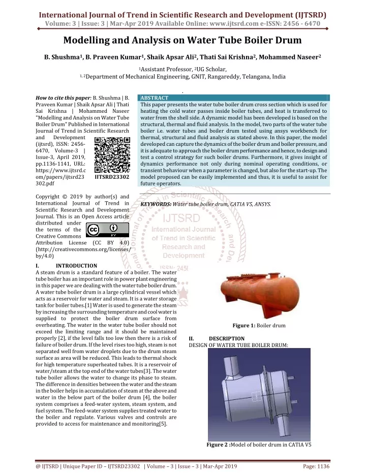
International Journal of Trend in Scientific Research and Development (IJTSRD) Volume: 3 | Issue: 3 | Mar-Apr 2019 Available Online: www.ijtsrd.com e-ISSN: 2456 - 6470 Modelling and Analysis on Water Tube Boiler Drum B. Shushma1, B. Praveen Kumar1, Shaik Apsar Ali2, Thati Sai Krishna2, Mohammed Naseer2 1Assistant Professor, 2UG Scholar, 1, 2Department of Mechanical Engineering, GNIT, Rangareddy, Telangana, India . How to cite this paper: B. Shushma | B. Praveen Kumar | Shaik Apsar Ali | Thati Sai Krishna | Mohammed Naseer "Modelling and Analysis on Water Tube Boiler Drum" Published in International Journal of Trend in Scientific Research and Development (ijtsrd), ISSN: 2456- 6470, Volume-3 | Issue-3, April 2019, pp.1136-1141, URL: https://www.ijtsrd.c om/papers/ijtsrd23 302.pdf Copyright © 2019 by author(s) and International Journal of Trend in Scientific Research and Development Journal. This is an Open Access article distributed under the terms of the Creative Commons Attribution License (CC BY 4.0) (http://creativecommons.org/licenses/ by/4.0) I. INTRODUCTION A steamdrum is a standard feature of a boiler. The water tube boiler has an important role in power plant engineering in this paper we are dealing with the water tube boiler drum. A water tube boiler drum is a large cylindrical vessel which acts as a reservoir for water and steam. It is a water storage tank for boiler tubes.[1] Water is used to generate the steam by increasing the surrounding temperature and cool water is supplied to protect the boiler drum surface from overheating. The water in the water tube boiler should not exceed the limiting range and it should be maintained properly [2], if the level falls too low then there is a risk of failure of boiler drum. If the level rises too high, steam is not separated well from water droplets due to the drum steam surface as area will be reduced. This leads to thermal shock for high temperature superheated tubes. It is a reservoir of water/steam at the top end of the water tubes[3]. The water tube boiler allows the water to change its phase to steam. The difference in densities between the water and the steam in the boiler helps in accumulation of steam at the above and water in the below part of the boiler drum [4], the boiler system comprises a feed-water system, steam system, and fuel system. The feed-water system supplies treated water to the boiler and regulate. Various valves and controls are provided to access for maintenance and monitoring[5]. ABSTRACT This paper presents the water tube boiler drum cross section which is used for heating the cold water passes inside boiler tubes, and heat is transferred to water from the shell side. A dynamic model has been developed is based on the structural, thermal and fluid analysis. In the model, two parts of the water tube boiler i.e. water tubes and boiler drum tested using ansys workbench for thermal, structural and fluid analysis as stated above. In this paper, the model developed can capture the dynamics of the boiler drum and boiler pressure, and it is adequate to approach the boiler drum performance and hence, to design and test a control strategy for such boiler drums. Furthermore, it gives insight of dynamics performance not only during nominal operating conditions, or transient behaviour when a parameter is changed, but also for the start-up. The model proposed can be easily implemented and thus, it is useful to assist for future operators. KEYWORDS: Water tube boiler drum, CATIA V5, ANSYS. IJTSRD23302 Figure 1: Boiler drum II. DESIGN OF WATER TUBE BOILER DRUM: DESCRIPTION Figure 2 :Model of boiler drum in CATIA V5 @ IJTSRD | Unique Paper ID – IJTSRD23302 | Volume – 3 | Issue – 3 | Mar-Apr 2019 Page: 1136
International Journal of Trend in Scientific Research and Development (IJTSRD) @ www.ijtsrd.com eISSN: 2456-6470 The above figure shows the complete model of the water tube boiler drum in CATIA V5 and figures 3 shows inside view of the water tube boiler drum with water tube coil. The above figures 4&5 represents the complete dimensions of the water tube boiler drum and dimensions of the coil inside the boiler using drafting DESCRIBING THE DESIGN OF WATER TUBE BOILER DRUM: Boiler drum is designed using CATIAv5 by using part design the helical spring will be designed which is called as water tube coil and by using sweep option the coil will be created and the material will be applied is copper , next the cap of boiler will be created by using one circle will be drawn with dimensions and by padding it will be converted into solid by using fillet the smooth edges will be created and by using shell option the inside hole created with some thickness of 2mm and next the lower part of the boiler will be created as the upper part is created and it will be joined with the upper part of boiler. III. ANALYSIS OF WATER TUBE BOILER DRUM: For the analysis of boiler drum we have used ANSYS 18.0 to analyse the fluid, thermal and structural analysis by applying finite element analysis Steps to be followed in ANSYS Analysis: 6 steps that could be followed to do analysis on any object ?Engineering data ?Geometry ?Meshing ?Setup ?Solution ?Results Figure 3: Internal view of a boiler drums Table 1 : MATERIALS USED IN DESIGN OF BOILER DRUM: S. No used The whole designed body made up of stain less steel Stainless steel made up of copper alloys The fluid which flows inside the boiler is water-liquid Material Description 1 Copper alloy The tubes inside the boiler are 2 3 Water liquid DIMENSIONAL VIEW OF BOILER DRUM: Figure 6 :Engineering data in ANSYS workbench The above figures show the selection of material, in this analysis we applied the mild steel for water tube boiler drum and copper alloy for the coil inside the water tube boiler drum. Figure 4 : Dimensions of the boiler drum using drafting Figure 5 : Dimensions of the coil inside the boiler using drafting Figure 7 :Meshing Model in Fluid Flow Fluent @ IJTSRD | Unique Paper ID - IJTSRD23302 | Volume – 3 | Issue – 3 | Mar-Apr 2019 Page: 1137
International Journal of Trend in Scientific Research and Development (IJTSRD) @ www.ijtsrd.com eISSN: 2456-6470 In the above figure the meshing operation is performed, we can change the size and shape of the elements and number of nodes and elements for finite element analysis Table 2 : Number of nodes and elements Domain Nodes Cap 36313 Coil 4233 All domains 40546 Elements 189713 13843 203556 Figure 9 :Streamlines of velocity The CFD analysis provided fluid velocity, pressure, temperature, and species concentration throughout the solution domain. During the analysis, the geometry of the system and boundary conditions such as inlet velocity and flow rate was changed to view their effect on thermal flow patterns or species concentration distribution. Figure 8 :Contours of total pressure In the above figure at the cool inlet the pressure is minimum that we can observe the pressure at outlet is maximum that is 8.9 MPA it equals to 89 bars Computer simulation can be employed to understand the thermal flow in the boiler and to solve operation problems with optimal solution. The simulation was conducted using a commercial CFD package for modelling heat and fluid flow and predict the performance of the boiler. The CFD helps engineers to optimize the operating conditions and also to improve the design of new boilers. The CFD predictions can explore the real phenomena which happen in places where experimental investigation is impossible or expensive. Performance parameters of a boiler like efficiency and evaporation ratio reduces with time, due to poor combustion, heat transfer fouling and poor operation and maintenance. Even for a new boiler reasons such as deterioration of fuel quality and water quality can result in poor performance of boiler. Efficiency testing helps us to find out how far the boiler efficiency drifts away from the best efficiency. Any observed abnormal deviations could therefore be investigated to pin point the problem area for necessary corrective action. Hence it is necessary to find out the current level of efficiency for performance evaluation. This is a pre-requisite for energy conservation action in industry. Figure 10 :Volume rendering in temperature Figure 11 : Streamline flow of velocity from hot inlet @ IJTSRD | Unique Paper ID - IJTSRD23302 | Volume – 3 | Issue – 3 | Mar-Apr 2019 Page: 1138
International Journal of Trend in Scientific Research and Development (IJTSRD) @ www.ijtsrd.com eISSN: 2456-6470 Figure 15 : Imported body temperature in static structural analysis Figure 12 :Formation of steam in boiler drums by the coil with streamline In the streamline flow of velocity steam flows with the maximum velocity of 5.1018 m/s as the minimum velocity of flow will be 1 m/s that we give at the cool inlet of drum. In this figure the maximum temperature obtained is 213°C and minimum temperature obtained is 26.62°C. Figure 16 :Total deformation of boiler drum in structural analysis Figure 13: Cross sectional view of model after thermal analysis In the above figure, the total deformation of the boiler drum in structural analysis is obtained at different surfaces of the boiler drum is minimum. Figure 17 :Maximum shear stress on boiler drum Figure 14 :Temperature after thermal analysis of boiler drum In the above figure, the maximum shear stress acting on the boiler drum contacting surface is 5.9 Pa. The above figure represents different temperature variants of the water tube boiler drum after thermal analysis; the temperature at the contacting surfaces of the two caps of the boiler drum is maximum and normal at the surface of the boiler because of the direct contact of the water. @ IJTSRD | Unique Paper ID - IJTSRD23302 | Volume – 3 | Issue – 3 | Mar-Apr 2019 Page: 1139
International Journal of Trend in Scientific Research and Development (IJTSRD) @ www.ijtsrd.com eISSN: 2456-6470 Figure 18 :Strain energy in structural analysis of boiler drum Figure 21: Safety factor of boiler drum IV We can observe the change in temperature with respect to time but in our analysis maximum temperature at time of the starting will be 219.17°Clater it decreased by 4°Cthat means 215.07°C After completion of analysis we can observe the, temperature in the following manner, Table 3: Time [s] Minimum [°C] Maximum [°C] 1.e-002 -142.21 2.e-002 -128.65 4.4806e-002 -102.72 9.0133e-002 -63.832 0.16694 -13.918 0.26694 0.67898 0.36694 2.7894 0.46694 4.6802 0.56694 6.515 0.66694 8.2828 0.76694 9.5387 0.86694 10.539 0.93347 11.176 1. 11.786 CFD Computed Temperature Data from CFD Results Average Temperature = 41.124 °C Maximum Temperature = 222.17 °C Minimum Temperature = 26.772 °C RESULTS 219.17 Figure 19 :Life of boiler drums in structural analysis 215.07 Figure 20 :Damage of boiler drum in static structural analysis In this static structural analysis the damage of the boiler drum is very less compared to other boiler drum, due to this the life of the boiler drum is increased Table 4: Comparative study of different boiler Input temperature Output temperature of water S. No Type of boiler Materials efficiency of steam Steel, copper alloy COIL Water tube boiler 500°C 215°C 80% 1 2 3 Flexible water tube Cast iron 210°C 180°C 78% solid drawn mild steel Babcock and Wilcox boiler 566°C 454°C 70-80% @ IJTSRD | Unique Paper ID - IJTSRD23302 | Volume – 3 | Issue – 3 | Mar-Apr 2019 Page: 1140
International Journal of Trend in Scientific Research and Development (IJTSRD) @ www.ijtsrd.com eISSN: 2456-6470 V. This paper mainly focuses on selection of suitable material for Boiler drum and analysis of water flow, structural analysis and thermal analysis of boiler drum Here, we can observe the flow of water from inlet to outlet for both cool liquid and hot steam in computational fluid dynamics analysis. We can observe the temperature changing inside the boiler drum from inlet to outlet from low temperature to high due to steam by using thermal analysis. We can observe the structural changes in the boiler drum due to high temperature steam flow using structural analysis. CONCLUSION VI. REFERENCES [1]Inkson, Mike, Analysis of new boiler technol B. Molloy, Modelling and predictive control of a Drum-type boiler. Ph.D. Thesis, Dublin City University, Dublin, 1997. [2]K. Begum, D. Mercy, H. Vedi, and M. Ramathilagam, “An intelligent model based level control of boiler drum,” International Journal ofEmerging Technology and Advanced Engineering(IJETAE), Vol. 3, No. 1, pp. 516– 521, Jan. 2013. [3]W. Zhou,W.Shichaoa,and J. Yanyan “Simulation of control of water level in boiler drum,” in World Automation Congress, 2012, pp.1–4 [4]IEC Company, Operation manual of 210 mw unit [5]Nassiriyah TPS (boiler, turbine, generator and transformer). Nassiriyah, 2001. [6]Dr. ogies, Thermal Energy Systems, 2012, pp. 1-9. @ IJTSRD | Unique Paper ID - IJTSRD23302 | Volume – 3 | Issue – 3 | Mar-Apr 2019 Page: 1141