Download
1 / 3
30 likes | 41 Views
This paper presents the techniques to mitigate transients caused by capacitor switching in the distribution system. It includes the theory of capacitive switching transients with different methods of mitigation. The paper uses MATLAB SIMULINK software package to simulate the specific mitigation devices. The mathematical calculations of different parameters such as transient voltages, current, and frequencies for each device are compared with obtained value from the simulations of each case study. Poonam Bhati | Mukesh Kumar Lodha "Design and Mitigation Techniques of MV- Capacitor Bank Switching Transients on 132 KV Substation" Published in International Journal of Trend in Scientific Research and Development (ijtsrd), ISSN: 2456-6470, Volume-3 | Issue-4 , June 2019, URL: https://www.ijtsrd.com/papers/ijtsrd25093.pdf Paper URL: https://www.ijtsrd.com/engineering/electrical-engineering/25093/design-and-mitigation-techniques-of-mv--capacitor-bank-switching-transients-on-132-kv-substation/poonam-bhati<br>

E N D
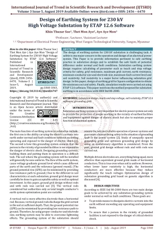
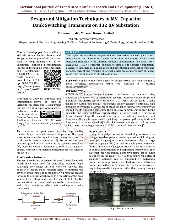
International Journal of Trend in Scientific Research and Development (IJTSRD) Volume: 3 | Issue: 4 | May-Jun 2019 Available Online: www.ijtsrd.com e-ISSN: 2456 - 6470 Design and Mitigation Techniques of MV- Capacitor Bank Switching Transients on 132 KV Substation Poonam Bhati1, Mukesh Kumar Lodha2 1M.Tech, 2Assistant Professor 1,2Department of Electrical Engineering, Sri Balaji College of Engineering & Technology, Jaipur, Rajasthan, India How to cite this paper: Poonam Bhati | Mukesh Kumar Lodha "Design and Mitigation Techniques of MV- Capacitor Bank Switching Transients on 132 KV Substation" Published in International Journal of Trend in Scientific Research and Development (ijtsrd), ISSN: 2456- 6470, Volume-3 | Issue-4, June 2019, pp.1207-1209, URL: https://www.ijtsrd.c om/papers/ijtsrd25 093.pdf Copyright © 2019 by author(s) and International Journal of Trend in Scientific Research and Development Journal. This is an Open Access article distributed under the terms of the Creative Commons Attribution License (CC BY 4.0) (http://creativecommons.org/licenses/ by/4.0) The riskiness of the capacitor switching effect is specified by the size of capacitor and the network impedance. The worst state occurs when the capacitor bank is energized close to a bank that is already connected [6]. To reduce transient overvoltage and inrush current during capacitor switching [7], there are various techniques to reduce that negative effects. Methods of transient’s mitigation are classified as follow [8, 9] Pre-insertion Resistors The use of pre-insertion resistors is one of classical methods which have been used for controlling capacitor-bank switching overvoltage but still effective remedy. The addition of pre-insertion resistors helps to minimize the severity of the transient by momentarily providing greater losses in the circuit, which leads to a reduction of the peak values of the voltage and current transients [10, 11]. The pre-insertion is accomplished by movable contacts where switch first contacts the resistor before making contact with the capacitor. ABSTRACT This paper presents the techniques to mitigate transients caused by capacitor switching in the distribution system. It includes the theory of capacitive switching transients with different methods of mitigation. The paper uses MATLAB/SIMULINK software package to simulate the specific mitigation devices. The mathematical calculations of different parameters such as transient voltages, current, and frequencies for each device are compared with obtained value from the simulations of each case study. Keywords: Capacitor Switching, Capacitor inrush current, switching transients, Surge arresters, Energization inrush, Pre- insertion of a resistor, MATLAB/SIMULINK INTRODUCTION POWER-FACTOR improvement increases transformers and lines capacities, decreases the power loss of distribution feeders, improves voltage drops and minimizes the electric bills for consumers [1, 2]. Inrush current leads to make failure for system equipment. This current usually generates extremely high transient over voltage [3]. Presence of capacitor banks in power systems provide many benefits but at the same time there are several problems appear during capacitor switching and have various effects on power quality. First one is transient overvoltage; the second is inrush current with high amplitude and frequency. The last is the capacitor switching that grows up the amplitude and frequency of harmonic signal [4]. As it is known over voltages occur in systems when the system voltage rises over 110 % of nominal rated voltage [5]. IJTSRD25093 Surge arrester It may be a gadget to ensure electrical gear from over- voltage homeless people caused by outside (lightning) or inner (exchanging) occasions. Moreover called a surge assurance gadget (SPD) or transitory voltage surge silencer (TVSS), this course of gadget is utilized to ensure hardware in control transmission and dispersion frameworks. (For customer gear assurance, distinctive items called surge defenders are utilized.) The vitality measure for different separator materials can be compared by motivation proportion. A surge arrester ought to have a moo motivation proportion, so that a surge occurrence on the surge arrester may be bypassed to the ground rather than passing through the apparatus. Fig. 1 Surge arrester @ IJTSRD | Unique Paper ID – IJTSRD25093 | Volume – 3 | Issue – 4 | May-Jun 2019 Page: 1207
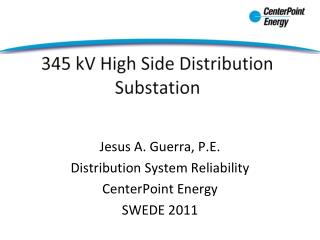
International Journal of Trend in Scientific Research and Development (IJTSRD) @ www.ijtsrd.com eISSN: 2456-6470 Benefits of Improving Power Factor 1.Industrial and commercial customers avoid power factor penalty charges. 2.Reduced currents results in reduced losses (I2R) 3.The efficiency of the power system is increased because real power flow is maximized and reactive power flow is minimized. 4.Voltage drop will be minimized. Voltages below equipment ratings cause reduced efficiency, increased current, and reduced starting torque in motors.[4] Problem Description Problem definition for the switching of capacitor several conventional methods is being used. Fixed reactor or pre inserted reactors are creating the resonance problem. Capacitor voltage levels are also needs to increase due to series reactor. Hence the DC series reactor is proposed to avoid the above mentioned issues. DC reactor provides the high impedance through a three phase coupling transformer during energizing instants. However during the steady state operation, DC reactor charges and discharges continuously. DESIGN LAYOUT OF 132 KV GSS Theoretical Background A small station is a part of an electrics living-stage, sending (power and so on) and distribution system. The group of parts of apparatus used to change some qualities (e.g. voltage, number of times, p.f. A.C. to D.C. and so on.) of an electrics supply is named a small station. Some of the main operations of small stations are: ?To receive energy transmitted at high voltage from the generating stations. ?To decrease the voltage to a value appropriate for local distribution. ?To provide switching facilities Electrical Substation An electrics substation is a less important station of an electric living-stage, sending (power and so on) and distribution system where electric force is greatly changed from high to low or the opposite using transformers Electric power may move liquid-like through several small stations between producing plant and user, and may be changed in electric force in several steps. A small station that has a step- up transformer increases the voltage while droping [process the current, while a step-down transformer drops the electric force while increasing the current for kept by man and trading, business like distribution. [52] Substations generally have: ?Switching equipment ?Protection equipment ?Control equipment ?One or more transformers Fig. 2 Block Diagram of Typical Electrical Supply System Fig. 3 MATLAB Model in Current limiting Reactor in 132 KV GSS @ IJTSRD | Unique Paper ID – IJTSRD25093 | Volume – 3 | Issue – 4 | May-Jun 2019 Page: 1208
International Journal of Trend in Scientific Research and Development (IJTSRD) @ www.ijtsrd.com eISSN: 2456-6470 1.Primary voltage (HV side) 132 kV-50 Hz, with a short circuit power of 2400 MVA, secondary voltage (MV side) 20 kV, insulated neutral. 2.Main transformer 132/20 kV, 40 MVA, short circuit voltage Ucc = 13%, copper losses 0.6%. 3.Ten departing lines of rated power 5 MVA and 10 km length each (line's parameters: parameters: series resistance 0.224 Ω /Km, series inductance 1.13mH/km, capacity 10.3nF/Km. 4.Line’s actual loads are 4.4 MW and 2.3 MVAR (PF 0.88) each Therefore the other two techniques to be considered to reduce the transients in voltages and current. But, also in lesser degree values. Still, its effect was noticeable and lasted for a few milliseconds. Hence, this is to conclude that practically current limiting reactor has the higher cost, here in MV switchgear surge arrester is the best choice to reduce transients with less complexity and cost of the equipment are concerned. Future Scope 1.Fast varying dynamic reactive power compensation. 2.Voltage sag mitigation at the time of Induction Motor starting. 3.Also it can be used for, at the time of long transmission & high rating of transformer charging. 4.Also it can be used for, to avoid resonance condition. REFERENCES [1]Y.V. Makarov And N.S. Moharari, “A Generalized Power System Reliability And Security Index”Members, IEEE, 2010 [2]Fengli Wang, “Reliability Evaluation Of Substations Subject To Protection Failures” Delft University Of Technology Delft, The Netherlands, July 2012 [3]Solomon Derbie, “Study On Reliability Improvement Of Adama City Power Supply Using Smart Grid Technology” Addis Ababa University Addis Ababa Institute Of Technology School Of Electrical And Computer Engineering,2014 Fault Current (Ampere) and Bus Voltage (Volt) [4]Lathrop S, Flynn B, ‘’ Distribution automation pilot at PacifiCorp’’. In: Western Energy Institute, 2006 operations conference, Costa Mesa, 5–7 Apr 2006 [5]Rich Hunt, J ohnCoursey and Stephen Hirsch, ‘’Simplifying Protection System Design for Distribution Substations’’ Presented a t the Texa s A&M 65th Annual Conference for Protective Relay Engineers College Station, TX April 2-5, 2012 [6]Kenneth Substation Solutions To Reduce Investment costs - Improved Availability And Reliability” Acapulco, gro., del 9 a 13 de julio del, 2001 Jabrand and HelgeNordli,”Innovative [7]Kamal preetsangar, ‘’Selection Of Appropriate Location Of Substation For Planning Of Distribution System‘’ Thapar University Patiala , June 2009 Line Current (Ampere) and ‘MOV’ Current (Ampere) [8]John D. McDonald, and al, ‘’Distribution Systems, Substations, and Integration Generation’’Springer Science and Business Media New York 2013 The current limiting reactor is an inductive coil having a large inductive reactances in comparison to their resistance and is used for limiting short circuit currents during fault conditions. Current-voltage reactors also reduced the voltage disturbances on the rest of the system. Conclusion Devices used for this power system are more vulnerable to power quality variations than equipment’s as applied in past decays. We have analyzed three techniques to mitigate the switching transients. It has been observed that practically current limiting reactor is expensive than the Other technique, for high voltage switchgear, surge arresters technique is used which is less expensive. But, ideally, pre insertion resistor method can have ideal component values to mitigate the capacitor switching transient. of Distributed [9]Mandelldalis, substations” a ncgraw-hill publication march 1980 “Design decisions for outdoor [10]San Juan, P.R., ‘’ Basic Guides for Electric Substation Design’’ Colegio de IngenierosAgrimensores de Puerto Rico Doeg Rodríguez and Angel T. Rodríguez Barroso March 31, 2010 [11]Shri V. Ramakrishna And ShriAlokgupta,” Reliability Of Power Supply” Member Director(Distribution) C.E.A 2012 (Power System) @ IJTSRD | Unique Paper ID – IJTSRD25093 | Volume – 3 | Issue – 4 | May-Jun 2019 Page: 1209