Download
1 / 7
70 likes | 79 Views
In this paper, single sided linear induction motor SLIM for driving the elevator system is designed. Differing from other motors, SLIM is simple in construction, less expensive, very suitable for linear application which is used from low speed to high speed application. Special machine adjustments and alignments are not necessary in SLIM because mechanical coupling and gears are not required. Thus, SLIM is superior to other linear and rotary motor. The single sided linear induction motor SLIM design, performance equations and design procedure are developed and its performance is predicted by using equivalent circuit model. End effects and edges effects are neglected in this study. The performance of the SLIM for different value of mechanical air gap are evaluated by using MATLAB. The effect of variation of such parameters on the performance of the machine is discussed. Aye Mya Mhway | Nan Win Aung | May Nwe Yee Tun "Design and Performance Analysis of Proposed Single-Sided Linear Induction Motor used in Elevator" Published in International Journal of Trend in Scientific Research and Development (ijtsrd), ISSN: 2456-6470, Volume-3 | Issue-1 , December 2018, URL: https://www.ijtsrd.com/papers/ijtsrd19005.pdf Paper URL: http://www.ijtsrd.com/engineering/electrical-engineering/19005/design-and-performance-analysis-of-proposed-single-sided-linear-induction-motor-used-in-elevator/aye-mya-mhway<br>

E N D
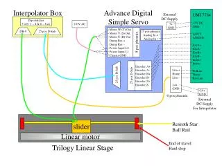
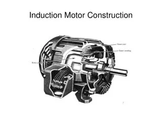
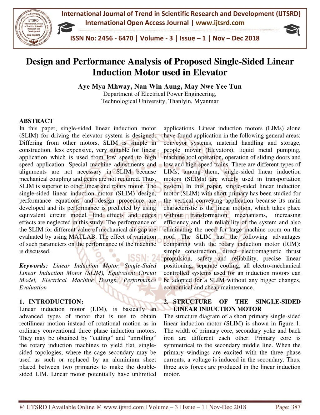
International Journal of Trend in Scientific Research and Development (IJTSRD) International Open Access Journal | www.ijtsrd.com ISSN No: 2456 - 6470 | Volume - 3 | Issue – 1 | Nov – Dec 2018 Design and Performance Analysis of Proposed Single-Sided Linear Induction Motor used in Elevator Aye Mya Mhway, Nan Win Aung, May Nwe Yee Tun Department of Electrical Power Engineering, Technological University, Thanlyin, Myanmar ABSTRACT In this paper, single-sided linear induction motor (SLIM) for driving the elevator system is designed. Differing from other motors, SLIM is simple in construction, less expensive, very suitable for linear application which is used from low speed to high speed application. Special machine adjustments and alignments are not necessary in SLIM because mechanical coupling and gears are not required. Thus, SLIM is superior to other linear and rotary motor. The single-sided linear induction motor (SLIM) design, performance equations and design procedure are developed and its performance is predicted by using equivalent circuit model. End effects and edges effects are neglected in this study. The performance of the SLIM for different value of mechanical air-gap are evaluated by using MATLAB. The effect of variation of such parameters on the performance of the machine is discussed. Keywords: Linear Induction Motor, Single-Sided Linear Induction Motor (SLIM), Equivalent Circuit Model, Electrical Machine Design, Performance Evaluation 1.INTRODUCTION: Linear induction motor (LIM), is basically an advanced types of motor that is use to obtain rectilinear motion instead of rotational motion as in ordinary conventional three phase induction motors. They may be obtained by “cutting” and “unrolling” the rotary induction machines to yield flat, single- sided topologies, where the cage secondary may be used as such or replaced by an aluminium sheet placed between two primaries to make the double- sided LIM. Linear motor potentially have unlimited applications. Linear induction motors (LIMs) alone have found application in the following general areas: conveyor systems, material handling and storage, people mover (Elevators), liquid metal pumping, machine tool operation, operation of sliding doors and low and high speed trains. There are different types of LIMs, among them, single-sided linear induction motors (SLIMs) are widely used in transportation system. In this paper, single-sided linear induction motor (SLIM) with short primary has been studied for the vertical conveying application because its main characteristic is the linear motion, which takes place without transformation efficiency and the reliability of the system and also eliminating the need for large machine room on the roof. The SLIM has the following advantages comparing with the rotary induction motor (RIM): simple construction, direct electromagnetic thrust propulsion, safety and reliability, precise linear positioning, separate cooling, all electro-mechanical controlled systems used for an induction motors can be adopted for a SLIM without any bigger changes, economical and cheap maintenance. 2.STRUCTURE OF LINEAR INDUCTION MOTOR The structure diagram of a short primary single-sided linear induction motor (SLIM) is shown in figure 1. The width of primary core, secondary yoke and back iron are different each other. Primary core is symmetrical to the secondary middle line. When the primary windings are excited with the three phase currents, a voltage is induced in the secondary. Thus, three axis forces are produced in the linear induction motor. mechanisms, increasing THE SINGLE-SIDED @ IJTSRD | Available Online @ www.ijtsrd.com | Volume – 3 | Issue – 1 | Nov-Dec 2018 Page: 387
International Journal of Trend in Scientific Research and Development (IJTSRD) ISSN: 2456-6470 Number of slot per pole per phase, Aluminum thickness, Width of stator, Mechanical air gap, Continuously, to obtain the target thrust in a Single- Sided Linear Induction Motor, the following equations are used. Synchronous velocity, v =1-s s v τ=2f τ λ=mq Length of primary (Stator), τ=3W +3W In this design, the number of slot is 12 and single- layer winding W =1.5W And then, get the value tooth width and slot width shown in figure 2. hy 1q =1 d=3mm W =1000mm g =5mm st m v (1) r Figure 1.Structure of the single-sided linear induction motor (SLIM) 3.DESIGN PROCEDURE OF SINGLE-SIDED LINEAR INDUCTION MOTOR The specifications of SLIM Targe thrust, F's : 16000 N Rated velocity, vr : Rated Slip, s : 10% Rated line voltage, V1: 400 V Number of phase, m : 3phase Number of poles, p : 4poles Frequency, f : 50 Hz Types of winding: Single Layer Winding And, this machine is supposed to be applied in the elevator, achieving vertical transportation with ascending/rising speed upwards, respectively. Therefore, the size of the cabin, total weight of cabin and necessary mechanical connection to it, and maximum allowable passenger and the average weight of each passenger are needed to know. All the necessary information are mentioned below Size of cabin,(height ×length ×width)cabin =2.5 ×2 ×1m3 Total weight of cabin and bearing, mcabin Number of passenger in one cabin, np Average weight of each passenger, mpassenger 3.1 Design of Primary (Stator) Stator unit is designed according to the following procedure. First, assign the constant values Permeability of free space, Volume resistivity of Copper, Volume resistivity of Aluminum Stator current density, Maximum tooth flux density, Maximum yoke flux density, Coil span in electrical radians, s Pole pitch, (2) Slot pitch, (3) 1 L =τp (4) (5) s 10 m/s s t (6) t s rv and acceleration a up to 10m/s and 2m/s2 ws Hs hs wt Figure.2 Dimension of Stator Slot Number of turn per phase, N =N pq (7) 1 c 1 Where number of turn per slot one until the target thrust is obtained. N is the number of turn per phase and set the N to one and increment it by 1 : 500kg : 5 : 75kg c Now, let assume the product of 1 arbitrary. And find, the value of stator current, ' ' 1 3 cos ph V between 0 and cos μ =4π×10 H/m ρ =19.27×10 Ωm rρ =28.85×10 Ωm 1J =6A/mm B =1.6Tesla B =1.3Tesla -7 F v (8) 0 = s r I -9 w -9 ' I Area of copper wire, A =J (9) ' w 1 2 1 tmax Total cross-sectional area of copper wire, ' c w A =N A ymax (10) p θ =π wt @ IJTSRD | Available Online @ www.ijtsrd.com | Volume – 3 | Issue – 1 | Nov-Dec 2018 Page: 388
International Journal of Trend in Scientific Research and Development (IJTSRD) ISSN: 2456-6470 3.2 Equivalent Circuit Model The equivalent parameters of SLIM can be determined using the per-phase equivalent circuit as shown in figure 3. 10 7 Cross-sectional area of slot, (11) ' w A = N A s c A Stator slot height, h =W (12) s s s θ I1 I2 Length of end connection, (13) p L = τ + X1 + ce 180 R1 Im V1 Effective stator width, W =W +L (14) Xm R2/s est st ce - - Mean length of one turn of the stator winding per phase, L =2W Length of copper wire per phase, Total length of copper wire, After assuming the value of Aluminum thickness of conducting layer, d, the magnetic air gap, calculated g =g +d And also find the equivalent stator width, W =W +g Gamma for calculating carter’s coefficient, Figure.3 Equivalent Circuit of Linear Induction Motor (15) w1 est ρ L Per-phase stator resistance, (28) w A w R = 1 L =N L (16) wt w 1 w1 Per-phase slot leakage reactance, W q (17) 3 p T =mL 2 1 st 2μ πf λ 1+ +λ +λ L N Lw w 0 s d e ce 1 (29) X = 1 p 0 g is Slot, differential and end connection permeance are ( s p s s 12W g 5 W λ = g 5+4 W λ =0.3(3k -1) Magnetizing reactance per phase, 2 0 seq w 1 m 2 e π pg ) (18) h 1+3k 0 m λ = e (19) seq st 0 (30) s d e s 2 W W 2g W 2g 4 π 2g (20) e p s s s γ= arctan -ln 1+ 0 0 0 24μ πfW k N τ λ (31) X = k =λ-γg g =k g 2μ fτ G= π (21) Carter’s coefficient, c 0 X G Effective air gap, (22) Per-phase rotor resistance, (32) m R = e c 0 2 Using the equivalent circuit parameters from the above equations (28), (29), (31) and (32),and the circuit diagram shown in figure 3, the rated value of impedance can be calculated by R j X s Z=R +jX +R +jX s 2 The goodness factor, (23) 0 ρ d r g e θ p Pitch factor, 2 (24) k =sin 2 p m (33) π Slot angle, α=mq (25) 1 1 2 m 1 ( ) Z Z α 2 α Re sinq Power factor the design motor, (34) = cos 1 Distribution factor, (26) k = d q sin2 1 V Z (35) The rated primary RMS phase current, 1 I = 1 Winding factor, k =k ×k (27) w p d @ IJTSRD | Available Online @ www.ijtsrd.com | Volume – 3 | Issue – 1 | Nov-Dec 2018 Page: 389
International Journal of Trend in Scientific Research and Development (IJTSRD) ISSN: 2456-6470 Then magnitude of magnetizing current, R s I = ×I R +X s h ,the volume of the yoke Making use of is V =L W h In addition, the volume of one tooth of the primary core is V =W Wh Since the teeth have uniform size, the volume of the total teeth is derived as ( ) teeth 1 tooth V = mpq V Where mpq1 is the number of slot in a primary core.So, the volume of the iron core of the primary V is V =V +V The weight of the entire iron core, The weight of copper wire, The weight of one primary unit iron core and copper wire, is easily obtained as W =W +Wc L , W and y st s 2 (36) (46) m 1 yoke s st y 2 2 m 2 Also the magnitude of secondary phase current be calculated from X I = ×I R +X s 2I can (47) tooth st t s (37) m 2 1 2 2 m 2 (48) The SLIM input active power, (38) = 1 1cos mV I iP The output power, (39) 2 1 2 2 P =P -mI R -mI R iron 0 i 1 2 (49) And then efficiency is calculated by following equation P η= ×100% P The electromagnetic force is given by P F =v 3.3 Required Force Calculation Resulting magnetomotive force (MMF), 4 2mk N I θ = πp By mean of MMF, the peak value of the normal component of the magnetic flux density is given by μ θ B = 2g Theoretically, the flux in the air gap is sinusoidal because of the sinusoidal voltage source. Thus, the average flux density gavg B can be gained, based on the relation with the peak value of that, i.e 2 B = B π The yoke of the primary core refer to the section at the top of the core showed in figure 2. B τ h =2B iron yoke teeth =ρ V (50) W iron i iron (40) 0 (51) W =ρ A T c i c w lw sF produced by a machine , consisting of W stator (52) (41) 0 stator iron s r h Number of primary unit, =1.2L (53) cabin n stator s And then, the total output thrust can be calculated as F =n F Now checking the require force by Newton’s Second Law, The mass of the whole rising system, m =n m +n W +m The moving resistance of the system D, consists of two components in this specific case, which are Rolling resistance, Where coefficient normally defined as 0.01-0.02 N/kg and 0.00015- 0.0003 N/kg. and aerodynamic resistance, (54) t stator s (42) w 1 m m (43) 0 m (55) gmax t p passenger stator stator cabin 0 D =m (c +c v ) (56) r t 1 2 r 1c and 2c are of correlation, (44) gavg gmax 1 2 (57) = rv A 2 D a (45) gavg Where ρ is the air density or bottom area of cabin y gmax 1.205kg/m and Ais the top 2m . 3 2 @ IJTSRD | Available Online @ www.ijtsrd.com | Volume – 3 | Issue – 1 | Nov-Dec 2018 Page: 390
International Journal of Trend in Scientific Research and Development (IJTSRD) ISSN: 2456-6470 Table1. Design of Primary Parameters Symbol Values Unit Copper wire size Diameter of wire Length of stator Width of stator Slot width s Tooth width t Slot height Yoke height Total moving resistance is given by D=D +D Now, making use of Newton’s Second Law of Motion, the force required to be produced by the propulsion system ( ) s t F =m a+g +D Where g is acceleration of gravity, Finally, t s F F becomes a greatly important criterion to decide whether this machine design is satisfied or not. 3.4 Design of Secondary The single-sided linear induction motor secondary (rotor) design contains conduction layer design and reaction plate design, it is illustrated in figure 4. (58) r a - 1 SWG Stator winding design - 7.62 mm s L 450 mm (59) ' W 1000 mm Stator core design st 9.8m/s . 2 W W s h h 14.7 22 32.73 12.51 mm mm mm mm ' y Table2. Design of Secondary Parameters Length of secondary Width of secondary Thick of conducting layer Thick of reaction plate The length of the secondary will be as long as the motion length. So, the length of secondary is not illustrated in table 2. The design data sheet of electrical parameters of SLIM is presented in table 3.In the electrical parameters design, neglect the core losses. Table3. Design Output of Electrical Parameters Parameters Symbol Values Unit Per-phase stator resistance Per-phase stator slot leakage reactance Per-phase magnetizing reactance Per-phase rotor resistance Supply current Input active power Output power Efficiency Power factor This motor is designed to move the total mass of 1643.5kg.It is needed 19.54kN output thrust with the rated velocity 10m/s. The outputs for the design motor are tabulated below table 4. Table4. Design Output of SLIM Parameters Symbol Values Unit Total output thrust Velocity Symbol Values Unit L W 1100 d se mm mm mm se 3 6 Conducting Layer Ws Hr Ls Reaction Plate Figure.4 Dimension of Secondary (Rotor) The secondary reaction plate design which can consist of either solid or laminated design. To improve performance, the reaction plate is coated with conduction sheet of either aluminium or copper. For standard operating, the reaction plate should not be any less than 6mm thick and the attached conducting sheet should not be any less than 3mm thick. The best thrust per size ratio is obtained. 2τ W =W +π Where se W is width of secondary and primary 4.DESIGN CALCULATION RESULTS OF SLIM According to the design procedure in section 3, design calculation result of single-sided linear induction motor are mentioned with the following tables. R 0.00356 Ω 1 X 0.1371 Ω 1 X 1.1795 Ω m R 0.2055 Ω 2 201.605 62.854 56.211 0.89 0.45 A kW kW % - 1I iP 0P η cos (60) se st W is width of st tF rv 22.5 10 kN m/s @ IJTSRD | Available Online @ www.ijtsrd.com | Volume – 3 | Issue – 1 | Nov-Dec 2018 Page: 391
International Journal of Trend in Scientific Research and Development (IJTSRD) ISSN: 2456-6470 5.PERFORMANCE CURVES OF SLIM The input data used for SLIM design in MATLAB program was given in above section(3) along with the slot geometry. The performance characteristics of the SLIM are shown in following figures. Also, output thrust and efficiency decrease when the design incorporates a large air gap. The goodness factor is inversely proportional to the air gap. Thus, it is clear that the air gap should be as small as is mechanically possible. The different performance values with varying air gap are shown in figure 7 and 8. When the air gap is changed, keeping all other parameters fixed, the efficiency slightly decreases with increasing air gap and the output thrust decreases as the air gap is increased. 4 Mechanical Characteristic 12x 10 10 8 4 14x 10 Force (N) 6 12 gm=3mm 4 10 X: 9.999 Y: 1.961e+004 gm=5mm 2 8 Force (N) vr=10m/s gm=10mm 6 0 0 2 4 6 8 10 12 Rotor Velocity (m/s) 4 Fig.5 Thrust (Force) Fs' versus rotor velocity vrof SLIM stator unit at a rated slip of 10%, a desired rotor velocity of 10m/s, a target thrust of 16kN and final thrust of 19.61kN 2 Vr=10m/s 0 0 2 4 6 8 10 12 Rotor Velocity (m/s) Fig.7Effect of mechanical air gap on thrust of SLIM at a rated slip of 10% and a target thrust of 16kN Changing Efficiency on Rotor Velocity 100 X: 9.999 Y: 89.99 90 100 80 90 70 80 60 Efficiency (%) 70 50 60 Efficiency (%) 40 50 30 40 20 30 10 vr=10m/s 20 0 0 2 4 6 8 10 12 10 Vr=10m/s Rotor Velocity (m/s) 0 Fig.6 Efficiency η versus rotor velocity vr of SLIM stator unit at a rated slip of 10%, a desired rotor velocity of 10m/s, a target thrust of 16kN 0 2 4 6 8 10 12 Rotor Velocity (m/s) Fig.8 Effect of mechanical air gap on efficiency of SLIM at a rated slip of 10% and a target thrust of 16kN Table5. Air Gap Effect on Thrust (Force) and Efficiency Air gap(mm) Thrust(kN) Efficiency(%) 3 21.66 5 19.16 10 15.18 6.PERFORMANCN EVALUATION OF SLIM BY CHANGING PARAMETER The performance of the SLIM based on this particular design is evaluated by varying certain parameter like the mechanical air gap. Based on this evaluation, the best possible value for this parameter is selected as shown in the following sections. 6.1 Effect of Mechanical Air Gap on Performance The length of the air gap plays the most critical role determining the characteristics of the machine. A large air gap requires a large magnetizing current and results in a smaller power factor. In the case of SLIM, exit-end zone losses increase with a larger air gap. 90 89.99 89.89 7.CONCLUSION In this paper, the equivalent circuit has been derived to analyze the performance of the short primary SLIM. So, from the parametric analysis it can be concluded that the input parameter like the length of @ IJTSRD | Available Online @ www.ijtsrd.com | Volume – 3 | Issue – 1 | Nov-Dec 2018 Page: 392
International Journal of Trend in Scientific Research and Development (IJTSRD) ISSN: 2456-6470 9.REFERENCES 1.Hoang, Viet Nam: “Design of A Single-Sided Linear Induction Motor”, Queensland, (2003). 2.IN., .Degree Project Electrical Power Engineering 120 Credits. Second Cycle. ,.Stockholm Sweden 2015. “Linear Induction Motor Investigation and Design for Articulated Funiculator”. YIFEI HU 3.Sarveswara Prasad Bhamidi: “Design of a Single- Sided Linear Induction Motor (SLIM) Using a User Interactive Computer Program”, M.sc. Thesis, University of Missouri- Columbia, May (2005). 4.Boldea, I., and Syed N. A: “The Induction Machine Handbook”., Electric Power Engineering Series, (2002) 5.Yamamura: “Theory of Linear Induction Motors”, 2nd Edition, John Wiley & Sons, Inc. New York, (1979). 6.http://www.electricalpowerenergy.com/Linear- induction-motor/ the mechanical air gap plays a very important role in the performance parameters, thrust and efficiency. As the length of the mechanical air gap of the machine increases thrust and efficiency of the machine decrease. Hence, based on the target values of rotor velocity and thrust, this parameter should be chosen which gives the best possible thrust closest to the target value at a required frequency. 8.ACKNOWLEDGMENTS The author is deeply grateful to Dr. Nan Win Aung, my dissertation supervisor and Daw May Nwe Ye Tun, my co-supervisor. The author also thanks to all teachers at Technological University (Thanlyin) and all who provided her with necessary assistance for this paper. The author wishes to express her guidance to all persons who helped directly or indirectly towards the successful completion of paper. Finally, the author wishes to express her special thanks to her parents for their support and encouragement to attain her destination without any trouble. University of @ IJTSRD | Available Online @ www.ijtsrd.com | Volume – 3 | Issue – 1 | Nov-Dec 2018 Page: 393