Download
1 / 5
50 likes | 65 Views
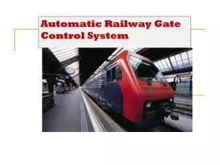
This paper investigates based on four IR sensor automatic control of railway gate using a microcontroller system. There are so many railway accidents happening due to the carelessness in manual operations or lack of worker. So, this paper describes four IR sensor based automatic control of railway gate system for saving precious human lives and preventing major disasters in railway track. Railway gate may be saved for the road users to prevent accidents in terms of train speed at a level crossing. Automatic railway gate control system is an innovative circuit which automatically controls the operation of railway gates detecting the arrival and departure of train at the gate. This automatic system can be replaced by the gates operated by the gatekeeper. The operation using Arduino UNO that integrated with other circuits involved such as power supply, IR sensors, light indicators, buzzer, and gate motors. The servo motor is used to control the open and close status of the railway crossing gate. The four IR sensors are placed on the railway tracks. The gate is closed when the first one senses the train and is opened when the second one senses the train. This operation is performed when the train is coming from the left side of the gate. When the train is coming from the right side, the third and fourth sensors is performed in the same operation. The red LED is HIGH when the gate is closed and the green LED is HIGH when the gate is opened. This system is based on software programming to operate the hardware structure. Program for four IR sensor based automatic control of railway gate system is based on Arduino UNO with C language. The main function of the design is Arduino UNO. Hay Man Oo | Ni Ni San Hlaing | Thin Thin Oo "Four IR Sensor Based Automatic Control of Railway Gate using Microcontroller" Published in International Journal of Trend in Scientific Research and Development (ijtsrd), ISSN: 2456-6470, Volume-3 | Issue-5 , August 2019, URL: https://www.ijtsrd.com/papers/ijtsrd26634.pdf Paper URL: https://www.ijtsrd.com/engineering/electronics-and-communication-engineering/26634/four-ir-sensor-based-automatic-control-of-railway-gate-using-microcontroller/hay-man-oo<br>

E N D
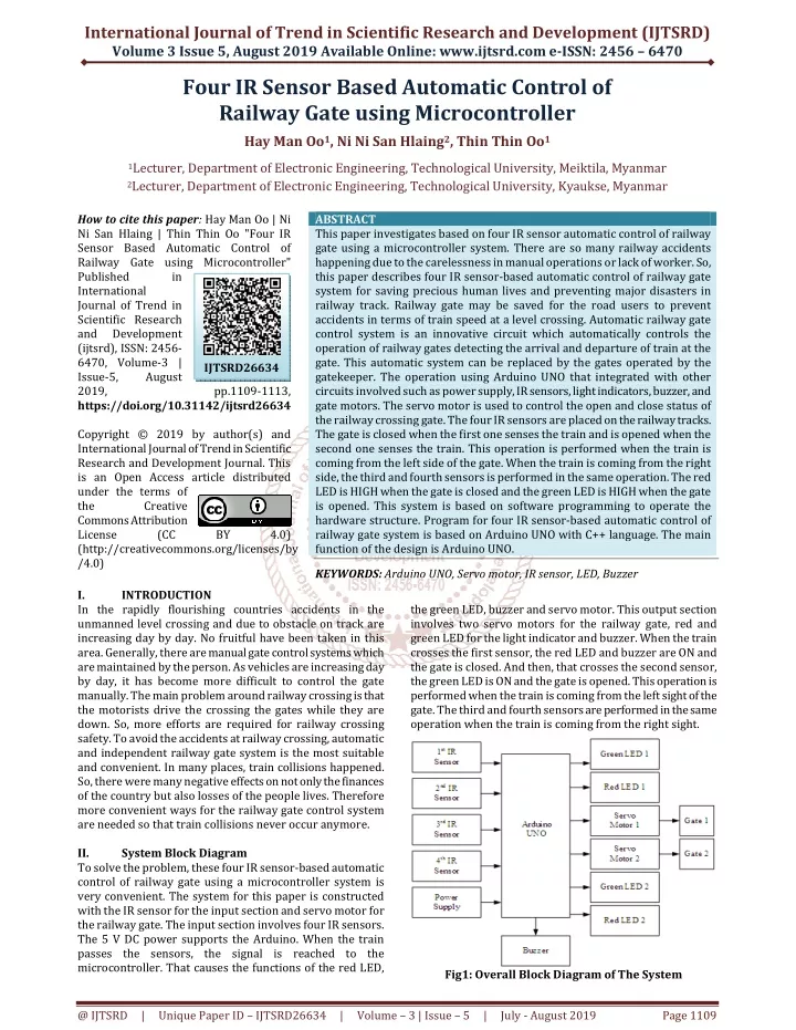
International Journal of Trend in Scientific Research and Development (IJTSRD) Volume 3 Issue 5, August 2019 Available Online: www.ijtsrd.com e-ISSN: 2456 – 6470 Four IR Sensor Based Automatic Control of Railway Gate using Microcontroller Hay Man Oo1, Ni Ni San Hlaing2, Thin Thin Oo1 1Lecturer, Department of Electronic Engineering, Technological University, Meiktila, Myanmar 2Lecturer, Department of Electronic Engineering, Technological University, Kyaukse, Myanmar How to cite this paper: Hay Man Oo | Ni Ni San Hlaing | Thin Thin Oo "Four IR Sensor Based Automatic Control of Railway Gate using Microcontroller" Published in International Journal of Trend in Scientific Research and Development (ijtsrd), ISSN: 2456- 6470, Volume-3 | Issue-5, August 2019, https://doi.org/10.31142/ijtsrd26634 Copyright © 2019 by author(s) and International Journal of Trend in Scientific Research and Development Journal. This is an Open Access article distributed under the terms of the Creative Commons Attribution License (CC (http://creativecommons.org/licenses/by /4.0) ABSTRACT This paper investigates based on four IR sensor automatic control of railway gate using a microcontroller system. There are so many railway accidents happening due to the carelessness in manual operations or lack of worker. So, this paper describes four IR sensor-based automatic control of railway gate system for saving precious human lives and preventing major disasters in railway track. Railway gate may be saved for the road users to prevent accidents in terms of train speed at a level crossing. Automatic railway gate control system is an innovative circuit which automatically controls the operation of railway gates detecting the arrival and departure of train at the gate. This automatic system can be replaced by the gates operated by the gatekeeper. The operation using Arduino UNO that integrated with other circuits involved such as power supply, IR sensors, light indicators, buzzer, and gate motors. The servo motor is used to control the open and close status of the railway crossing gate. The four IR sensors are placed on the railway tracks. The gate is closed when the first one senses the train and is opened when the second one senses the train. This operation is performed when the train is coming from the left side of the gate. When the train is coming from the right side, the third and fourth sensors is performed in the same operation. The red LED is HIGH when the gate is closed and the green LED is HIGH when the gate is opened. This system is based on software programming to operate the hardware structure. Program for four IR sensor-based automatic control of railway gate system is based on Arduino UNO with C++ language. The main function of the design is Arduino UNO. KEYWORDS: Arduino UNO, Servo motor, IR sensor, LED, Buzzer the green LED, buzzer and servo motor. This output section involves two servo motors for the railway gate, red and green LED for the light indicator and buzzer. When the train crosses the first sensor, the red LED and buzzer are ON and the gate is closed. And then, that crosses the second sensor, the green LED is ON and the gate is opened. This operation is performed when the train is coming from the left sight of the gate. The third and fourth sensors are performed in the same operation when the train is coming from the right sight. IJTSRD26634 pp.1109-1113, BY 4.0) I. In the rapidly flourishing countries accidents in the unmanned level crossing and due to obstacle on track are increasing day by day. No fruitful have been taken in this area. Generally, there are manual gate control systems which are maintained by the person. As vehicles are increasing day by day, it has become more difficult to control the gate manually. The main problem around railway crossing is that the motorists drive the crossing the gates while they are down. So, more efforts are required for railway crossing safety. To avoid the accidents at railway crossing, automatic and independent railway gate system is the most suitable and convenient. In many places, train collisions happened. So, there were many negative effects on not only the finances of the country but also losses of the people lives. Therefore more convenient ways for the railway gate control system are needed so that train collisions never occur anymore. II. System Block Diagram To solve the problem, these four IR sensor-based automatic control of railway gate using a microcontroller system is very convenient. The system for this paper is constructed with the IR sensor for the input section and servo motor for the railway gate. The input section involves four IR sensors. The 5 V DC power supports the Arduino. When the train passes the sensors, the signal is reached to the microcontroller. That causes the functions of the red LED, INTRODUCTION Fig1: Overall Block Diagram of The System @ IJTSRD | Unique Paper ID – IJTSRD26634 | Volume – 3 | Issue – 5 | July - August 2019 Page 1109
International Journal of Trend in Scientific Research and Development (IJTSRD) @ www.ijtsrd.com eISSN: 2456-6470 The flowchart shown in Fig.2 is for the operation of the system. In this system, Arduino UNO is used as the control system consists of Step 1 : Start Step 2 : Initialize the two servo motors are 90º Step 3 : Initialize the four IR sensors Step 4 : Initialize green LEDs in the light indicators are HIGH Step 5 : Check 1st and 3rd IR sensors. If 1st and 3rd IR sensors are LOW, red LEDs are HIGH and green LEDs are LOW in the light indicators. Then, Buzzer is ON and the two servo motors are 0º. Step 6 : Check 2nd and 4th IR sensors. If 2nd and 4th IR sensors are LOW, green LEDs are HIGH and red LEDs are LOW in the light indicators. Then, Buzzer is OFF and the two servo motors are 90º. Step 7 : Exit III. A.Software Implementation The software implementation is the Arduino IDE based software environment. A program written with the Arduino IDE is called a sketch. Sketches are saved on the development computer as text files with the file extension .ino. Arduino Software (IDE) saved sketches with the extension .pde. A minimal Arduino C/C++ program consists of only two functions: setup (): This function is called once when a sketch starts after power-up or reset. It is used to initialize variables, input and output pin modes, and other libraries needed in the sketch. Loop (): After setup () function exits (ends), the loop () function is executed repeatedly in the main program. It controls the board until the board is powered off or is reset. Software Implementation for IR Sensor The software programming language for the IR sensor is very simple. The setup function follows the declaration of the LED pin is output and the IR pin is input by using to set pinMode. Besides, it is also declared to begin serial to show the result on the serial monitor. pinMode (ledPin, OUTPUT); pinMode (irPin, INPUT); Serial.begin (9600); The loop function includes the code to be executed continuously reading the IR pin and triggering the LED pin. While the LED pin is HIGH, the result shows “Object Detected” on the serial monitor. digitalWrite (ledPin, HIGH); Serial.println ("Object detected!"); But the result is showed as “No Object” while the LED pin is LOW. digitalWrite (ledPin, LOW); Serial.println ("NO Object"); Software Implementation for Servo Motor The programming language is written as the simplest form so that it is nothing to have any problem to understand. The setup function for the servo motor is declared the orange pin of the motor is input by using myservo. attach and also declared begin serial to show the result on the serial monitor. myservo.attach (10); Serial.begin (9600); The loop function for the servo motor includes reading the input pin and triggering the output by using myservo.write. While myservo.write is 0º, the result show “0” on the serial monitor and the result is showed “90” while myservo.write is 90º. And the delay time is one second. myservo.write (0); Serial.println ("0"); delay (1000); myservo.write (90); Serial.println ("90"); delay (1000) Software Implementation for the System The software programming for the operation is mainly used if statement. The setup function for the system is declared Implementation Fig 2: Overall System Flowchart @ IJTSRD | Unique Paper ID – IJTSRD26634 | Volume – 3 | Issue – 5 | July - August 2019 Page 1110
International Journal of Trend in Scientific Research and Development (IJTSRD) @ www.ijtsrd.com eISSN: 2456-6470 the four IR sensors are the input and the two light indicators and buzzer are the output by using pinMode. And the two servo motors are declared by using servo. attach language. The loop function for this operation includes reading the input sensor by using digitalRead and triggering the output by using digitalWrite. For the servo motor, servo. write a language is used. And the delay time is also included. f=digitalRead (firstsensor); s=digitalRead (secondsensor); t=digitalRead (thirdsensor); u=digitalRead (fourthsensor); Software Implementation for the First and Second Sensors The loop function for the first sensor is LOW and the second sensor is HIGH that means the train is sensed by the first sensor is declared the red LEDs in the light indicators are HIGH by using digitalWrite. And also declared buzzer which is the warning alarm for the road users is HIGH and the gate is closed. digitalWrite (buzzer, HIGH); servo1.write (90); servo2.write (90); And the loop function for the train is sensed by the second sensor is declared the green LEDs in the light indicators are HIGH by using programming language digitalWrite. The buzzer is LOW and the gate is opened again. digitalWrite (buzzer, LOW); servo1.write (0); servo2.write (0); Software Implementation for the Third and Fourth Sensors The loop function is declared the same operation of the first sensor is sensed for the third sensor is LOW and the fourth sensor is HIGH with the programming language digitalWrite. digitalWrite (gled1, LOW); digitalWrite (gled2, LOW); digitalWrite (rled1, HIGH); digitalWrite (rled2, HIGH); When the fourth sensor has sensed the train, the loop function includes the green LEDs in the light indicators are HIGH and the red is LOW. And buzzer is also LOW, the gate is opened again. This is the same operation when the second sensor is LOW. digitalWrite (gled1,HIGH); digitalWrite (gled2,HIGH); digitalWrite (rled1,LOW); digitalWrite (rled2,LOW); Software Implementation for Normal Situation When no train is coming, all the four IR sensors are HIGH. The loop function is declared the green LEDs are HIGH and the red LEDs are LOW. The buzzer is also LOW and the gate is opened. The use of programming language is digitalWrite and servo.write. servo1.write (0); servo2.write (0); B.Implementation by Hardware Fig3: Overall Circuit Diagram of the System This circuit is constructed with three main sections. The first section is IR sensors which are the input section. The second one is servo motors which are the output section. And the last one is the microcontroller Arduino UNO. The first and third IR sensors are placed together at the left side of the gate and the second and fourth IR sensors are also placed together at the right side of the gate. But the first sensor is connected to digital pin 2 and the third sensor is connected to digital pin 11 of the Arduino board for the gate is closed. Also again, the second is connected to digital pin3 and the fourth is connected to digital pin 12 of the Arduino board for the gate is opened. The two servo motors are used for the railway gate in this operation. These are connected to digital pin 9 and 10 of the Arduino board. And then, the whole system is based on software programming to operate the hardware structure. Program for the railway gate control system is based on Arduino UNO with C++ language. The main function of design is Arduino UNO. When the train is coming from the left side of the gate, the first sensor senses this train. This sensor sends the signal to the microcontroller. The red LEDs of the light indicators are HIGH at once. After one second, the servo motors change 90º that means the gate is closed and the buzzer is HIGH. This buzzer is the additional operation for the road users’ safety. And then, the train is crossing in front of the second sensor again. The signal arrives at the microcontroller so green LEDs of the light indicators are HIGH and the servo motors change 0º again that means the gate is opened. When the train is coming from the right side of the gate, the third and fourth sensors are performed the same operation as the first and second ones. The green and red LEDs in the first light indicator are connected to digital pin 4 and 5 of the microcontroller and in the next one are connected to digital pin 6 and 7. Besides the output pin of the buzzer is connected to digital pin 8 of the Arduino UNO board. @ IJTSRD | Unique Paper ID – IJTSRD26634 | Volume – 3 | Issue – 5 | July - August 2019 Page 1111
International Journal of Trend in Scientific Research and Development (IJTSRD) @ www.ijtsrd.com eISSN: 2456-6470 IV. The operation is constructed with four IR sensors. The first and third IR sensors are placed together at the left side of the gate and the second and fourth IR sensors are also placed together at the right side of the gate. But the first and third sensors are connected to digital pin 2 of the Arduino board for the gate is closed. Also again, the second and fourth sensors are connected to digital pin 3 of the Arduino board for the gate is opened. The two servo motors are used for the railway gate in this operation. These are connected to digital pin 9 and 10 of the Arduino board. The two light indicators are placed on each other side of the railway gate. The first indicator is connected to the digital pins 4 and 5. Another one is connected to the digital pins 6 and 7 of the Arduino UNO board. The buzzer is connected to the digital pin 8 as the additional operation. Result for the First and Second IR Sensors If the train is coming from the left side of the gate, the operation is performed according to the first and the second sensors. At the first, the train is crossed in front of the first sensor, the loop function declared the two light indicators show the red LEDs, the buzzer is HIGH and the servo motor is 90º that means the gate is closed. And then the train is crossed in front of the second sensor, the loop function declared the two light indicators show the green LEDs, the buzzer in LOW and the servo motor is 0º that means the gate is opened. Results Fig6: Result for the Third IR Sensor Fig7: Result for the Fourth IR Sensors Result for the Normal Situation If the nothing train is coming situation, the if the statement includes the green LEDs are HIGH and the red LEDs are LOW in the two light indicators, the buzzer is LOW and the servo motor is 0º that means the gate is opened. This situation is generally the same as the operation of the second and fourth sensors. Fig4: Result for the First IR Sensor Fig8: Result for the Normal Situation V. Four IR sensor-based automatic control of railway gate using a microcontroller system is centered on the idea of reducing human involvement for closing and opening the railway gate which allows and prevents accidents near the level crossing. The railway gate is a cause of many deaths and accidents. Hence, automating the gate can bring about a ring of surety to controlling the gates. So, automating this process reduces the chances of the gate failures and reduces the errors made by the gatekeepers. The accidents are avoided at the place where there is no person to manage the railway crossing Conclusion Fig5: Result for the Second IR Sensor Result for the Third and Fourth IR Sensors If the train is coming from the right side of the gate, the operation is performed according to the third and the fourth sensors. The loop function for the third IR sensor LOW is the same for the first IR sensor. Besides the loop function for the fourth IR sensor LOW is the same for the second IR sensor. @ IJTSRD | Unique Paper ID – IJTSRD26634 | Volume – 3 | Issue – 5 | July - August 2019 Page 1112
International Journal of Trend in Scientific Research and Development (IJTSRD) @ www.ijtsrd.com eISSN: 2456-6470 [4]Sankaraiah Siaah, Miza Sajid Ali Baig, Narsappa Reddy: Automatic Railway Gate Control System Using IR and Pressure Sensors with Voice Announcement, Volume-3, Issue-3, July-2015. gates. So, this control system offers an effective way to reduce the occurrence of railway accidents. And this can also contribute a lot of benefits either to the road users or to the railway management. Since the design is completely automated it can be used in remote villages where no station master or lineman is present. IR sensors are placed at the two sides of the gate. It is used to sense the arrival and departure of the train. This system uses the servo motors to open and close the gates automatically. VI. REFERENCES [1]Dwarakanath S K, Sanjay S B, Soumya G B, Arjun V, Vivek R: Arduino Based Automatic Railway Gate Control and Obstacle Detection System, Volume-5, Issue-5, May- 2016. [5]Tarun Agarwal: Servo Motor: Basic, Theory and Working Principle, 2015. [6]Acy M. Kottalil, Abhijith S, Ajmal M M, Abhilash L J, Ajith Babu: Automatic Railway Gate Control System, Volume- 3, Issue-2, February-2014. [7]Allison M. Okamura, Stanford University: Arduino Programming Language, 2014. [8]Fakrul Syazwan: Arduino Infrared Collision Avoidance, 28-Mar-2012. [2]Harshul Balani, Charu Gupta, Kratika Sukhwal: Advanced Safety Application for Railway Crossing, Volume-3, Issue-12, December-2015. [9]Ahmad Hafizi Bin Mohamad: Automatic Railway Gate Control By Using Microcontroller, May-2011. [10]Brian W. Evans: Arduino Programming Notebook, First Edition, 2007. [3]Joseph Henry: Buzzer, 22-May-2015. [11]Vijay Kumar Peddinti, Light Emitting Diodes, 2006. @ IJTSRD | Unique Paper ID – IJTSRD26634 | Volume – 3 | Issue – 5 | July - August 2019 Page 1113