Download
1 / 4
40 likes | 42 Views
Clinching is a mechanical joining method. Is it utilized in automobile industry as an alternative method to resistance spot welding. Considering that various types of materials are joined in car body production, PVD coatings are used to increase the lifetime of the clinching tools. Hot dip galvanized steel sheets were used for joining by clinching method. The zirconium nitride ZrN PVD coating was deposited on the surfaces of clinching tool. The loss of cohesion properties of coating was observed at punchu00c2u00b4s R0.2 radius after 300 clinched joints. FEM analysis was used to show the punchu00c2u00b4s critical part when the tool is under load. Lubou00c5u00a1 Kau00c5u00a1cu00a1k | Renu00e2 Kubu00adk "Influence of Elastic Deformations on the Adhesion of the ZRN Coating on the Clinching Tool" Published in International Journal of Trend in Scientific Research and Development (ijtsrd), ISSN: 2456-6470, Volume-4 | Issue-1 , December 2019, URL: https://www.ijtsrd.com/papers/ijtsrd29856.pdf Paper URL: https://www.ijtsrd.com/engineering/mechanical-engineering/29856/influence-of-elastic-deformations-on-the-adhesion-of-the-zrn-coating-on-the-clinching-tool/lubou0161-kau0161cu00e1k<br>

E N D
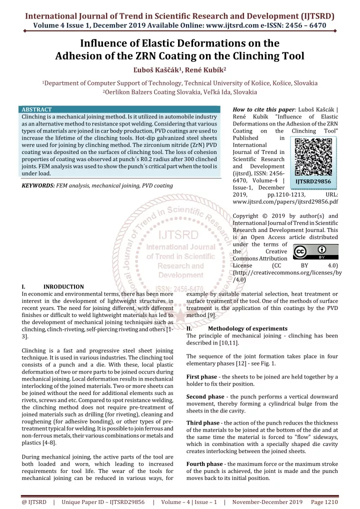
International Journal of Trend in Scientific Research and Development (IJTSRD) Volume 4 Issue 1, December 2019 Available Online: www.ijtsrd.com e-ISSN: 2456 – 6470 Influence of Elastic Deformations on the Adhesion of the ZRN Coating on the Clinching Tool Ľuboš Kaščák1, René Kubík2 1Department of Computer Support of Technology, Technical University of Košice, Košice, Slovakia 2Oerlikon Balzers Coating Slovakia, Veľká Ida, Slovakia ABSTRACT Clinching is a mechanical joining method. Is it utilized in automobile industry as an alternative method to resistance spot welding. Considering that various types of materials are joined in car body production, PVD coatings are used to increase the lifetime of the clinching tools. Hot-dip galvanized steel sheets were used for joining by clinching method. The zirconium nitride (ZrN) PVD coating was deposited on the surfaces of clinching tool. The loss of cohesion properties of coating was observed at punch´s R0.2 radius after 300 clinched joints. FEM analysis was used to show the punch´s critical part when the tool is under load. KEYWORDS: FEM analysis, mechanical joining, PVD coating How to cite this paper: Luboš Kašcák | René Kubík "Influence Deformations on the Adhesion of the ZRN Coating on the Published in International Journal of Trend in Scientific Research and Development (ijtsrd), ISSN: 2456- 6470, Volume-4 | Issue-1, December 2019, pp.1210-1213, www.ijtsrd.com/papers/ijtsrd29856.pdf Copyright © 2019 by author(s) and International Journal of Trend in Scientific Research and Development Journal. This is an Open Access article distributed under the terms of the Creative Commons Attribution License (CC (http://creativecommons.org/licenses/by /4.0) of Elastic Clinching Tool" IJTSRD29856 URL: BY 4.0) I. In economic and environmental terms, there has been more interest in the development of lightweight structures in recent years. The need for joining different, with different finishes or difficult to weld lightweight materials has led to the development of mechanical joining techniques such as clinching, clinch-riveting, self-piercing riveting and others [1- 3]. Clinching is a fast and progressive steel sheet joining technique. It is used in various industries. The clinching tool consists of a punch and a die. With these, local plastic deformation of two or more parts to be joined occurs during mechanical joining. Local deformation results in mechanical interlocking of the joined materials. Two or more sheets can be joined without the need for additional elements such as rivets, screws and etc. Compared to spot resistance welding, the clinching method does not require pre-treatment of joined materials such as drilling (for riveting), cleaning and roughening (for adhesive bonding), or other types of pre- treatment typical for welding. It is possible to join ferrous and non-ferrous metals, their various combinations or metals and plastics [4-8]. During mechanical joining, the active parts of the tool are both loaded and worn, which leading to increased requirements for tool life. The wear of the tools for mechanical joining can be reduced in various ways, for INRODUCTION example by suitable material selection, heat treatment or surface treatment of the tool. One of the methods of surface treatment is the application of thin coatings by the PVD method [9]. II. Methodology of experiments The principle of mechanical joining - clinching has been described in [10,11]. The sequence of the joint formation takes place in four elementary phases [12] - see Fig. 1. First phase - the sheets to be joined are held together by a holder to fix their position. Second phase - the punch performs a vertical downward movement, thereby forming a cylindrical bulge from the sheets in the die cavity. Third phase - the action of the punch reduces the thickness of the materials to be joined at the bottom of the die and at the same time the material is forced to "flow" sideways, which in combination with a specially shaped die cavity creates interlocking between the joined sheets. Fourth phase - the maximum force or the maximum stroke of the punch is achieved, the joint is made and the punch moves back to its initial position. @ IJTSRD | Unique Paper ID – IJTSRD29856 | Volume – 4 | Issue – 1 | November-December 2019 Page 1210
International Journal of Trend in Scientific Research and Development (IJTSRD) @ www.ijtsrd.com eISSN: 2456-6470 Initial state of the surface morphology of the punch and die was observed by scanning electron microscopy in potentially critical areas of the tools - perpendicular to the axis of the cylindrical surface of the punch and die. These areas were named as the tip (V), the tip radius (RV) and the surroundings of the tip (OV) (see Fig. 3). Fig.1. Clinching – creation of the joint [13] The tool for mechanical joining by clinching consists of a punch with a diameter of the active part ø5 mm and a punch with a cavity diameter of ø 7 mm (Fig. 2). The geometry of the joint, which was created by the clinching, directly affects the resulting characteristics in terms of joint strength and load-bearing capacity, the clinching joint geometry itself depends on the geometry of the punch, die and selected process parameters [1]. Fig.3.The exposed areas of the punch Since no significant degradation phenomena were observed on the die during joining, the focus was mainly on the punch. III. results and discussion Fig. 4 shows the morphology of the ZrN coating in the region of the tip of the punch (V) in a direction perpendicular to its face. This surface condition is the initial state of the tool after coating deposition. The surface after deposition had a characteristic texture as a result of the surface grinding applied. a) b) Fig.2. Clinching tool dimensions: a) die, b) punch PVD coating of the ZrN type was deposited on the punch and die by the LARC method. The tool used was a tool steel grade 1.3343 with a carbon content of up to 0.9%. The chemical composition of the mentioned tool steel is shown in Tab. I. TABLE I. CHEMICAL COMPOSITION OF STEEL 1.3343 IN WT [%] C Mn 0.9 0.33 0.019 0.005 Si Cr 0.31 3.88 The clinching was used to join a 0.8 mm thick H220PD hot- dip galvanized micro-alloyed steel sheets with a force of 7 kN. Sample sizes for joining 40x90 mm with 30 mm lap overlap were determined according to STN 05 1122 standard. The basic mechanical properties and the chemical composition of steel H220PD are shown in Tab. II and III. TABLE II. CHEMICAL COMPOSITION OF STEEL 1.3343 IN WT [%] RE[MPA] RM[MPA] A80[%] 220÷280 340÷410 TABLEIII.CHEMICALCOMPOSITIONOFSTEEL1.3343INWT [%] C Mn 0.01 0.43 0.05 0.04 Si Cr 0.12 0.04 0.01 0.03 Fig.4. Initial state of ZrN coating in the area V The stress concentrators in the form of technological notches have been identified as a result of machining by turning to the desired dimension in initial state in the area of the tip radius (RV), as seen in Fig. 5. The surface in this area was not treated to the specified surface roughness Ra 0.2 µm. For this reason, the RV area was identified as critical. During the joining of 0.8 mm thick sheets of H220PD with a joining force of 7000 N, the ZrN coating was damaged on the punch after 150 joints were produced. The coating was damaged in the RV area along the entire circumference of the cylindrical surface of the punch tip in the width of 100 to 200 µm. This phenomenon is documented in Fig. 6. P S Mo 4.76 V 1.85 A0[MM] 0.8 32 P Al V Ti Fig.5. Initial state of ZrN coating in the area RV @ IJTSRD | Unique Paper ID – IJTSRD29856 | Volume – 4 | Issue – 1 | November-December 2019 Page 1211
International Journal of Trend in Scientific Research and Development (IJTSRD) @ www.ijtsrd.com eISSN: 2456-6470 b) Fig.6. Decohesion of ZrN coating in the area RV During the joining, the punch in the third phase of clinching is under pressure load caused by the contact between the punch and the deformed reinforced sheets, which at the same time reach the tip of the die and the whole system behaves like a rigid material. The level of stresses and elastic deformations in the critical area of the RV punch was characterized by FEM modeling of the partial (third) phase of material joining by the clinching method. Modeling of this partial operation was performed as a planar, axially symmetrical model (Fig. 7). The sheets were modeled as an ideal plastic model and the punch was modeled as an elastic model (E = 210 GPa in both cases). Fig.8. FEM model of the punch with: a) R = 0.5 mm, b) R = 0 mm The simulation confirmed the concentration of elastic deformations in the critical area of the tip radius when the punch is loaded with 7000 N. The level of elastic deformations in the critical area of the punch RV is nearly twice that of an ideal sharp R0 mm transition compared to the tip radius R0.5 mm. Changing the radius in this region affects the stress-strain state at the coating-substrate interface and can thus affect the adhesive properties of the thin layer. At the thin coating-substrate interface, nucleation occurs and spreads further. Conclusion The advantages of mechanical joining by clinching consists in the use of economical and simple equipment, there is no thermal degradation of the material, degradation of metal and organic coatings; the method is suitable for joining materials with different coatings and thicknesses. The process of damaging the ZrN coating on the punch in the critical region of the projection radius is the result of multiple effects. Technological notches in the critical area of the tool as a result of mechanical machining cause stress concentrations that are greater than the stresses caused by the contact of the tool with the sheets to be joined. Residual stresses occurred during the deposition of the ZrN coating on the substrate. The combination of these stresses in the critical region of RV is higher than the adhesive strength of the coating-substrate system, resulting in crack formation and further propagation. The ZrN coating delaminates and the substrate is exposed to the joined material. FEM simulation of the partial operation of the joining method showed, that the intensity of the applied stresses and elastic deformations can be varied by changing the radius of curvature on the transition face of the face to the punch protrusion. Acknowledgment Author is grateful for the support of experimental works by project KEGA 065TUKE-4/2017 - Innovation of educational process in education of CAD/CAM/CAE systems using computational cluster GRID and project APVV-17-0381 - Increasing the efficiency of forming and joining parts of hybrid car bodies. Fig.7. Boundary conditions for simulation of clinching Two RV cases were simulated: the first one (real) as with R0.5 mm and the second one as the ideal sharp with R0 mm (Fig. 8). a) @ IJTSRD | Unique Paper ID – IJTSRD29856 | Volume – 4 | Issue – 1 | November-December 2019 Page 1212
International Journal of Trend in Scientific Research and Development (IJTSRD) @ www.ijtsrd.com eISSN: 2456-6470 [8]A. Breda, S. Coppieters, and D. Debruyne, “Equivalent modelling strategy for a clinched joint using a simple calibration method,” Thin-Walled Structures, vol. 113, p. 1-12, 2017. References [1]Ľ. Kaščák, J. Mucha, J. Slota, and E. Spišák, “Application of modern joining methods in car production,” Oficyna Wydawnicza Politechniki Rzeszowskiej, Rzeszów, 2013, 143 p. [9]Ľ. Kaščák, E. Spišák, R. Kubík, and J. Mucha, “Finite element calculation of clinching with rigid die of three steel sheets,” Strength of Materials, vol. 49, p. 488-499, 2017. [2]J. Varis, “Ensuring the integrity in clinching process,” Journal of material processing technology, vol. 10, p. 277-285, 2006. [3]V. Hamel, et al., “Finite element modeling of clinch forming with automatic remeshing,” Computers and Structures, vol. 77, p. 185-200, 2000. [10] Ľ. Kaščák, and E. Spišák, “Clinching of combination of high-strength steel sheets and aluminium sheets,” Transfer inovácií, vol. 30, p. 215-218, 2014. [4]F. Lambiase, A. Paoletti, and. A. Di Ilio, “Advances in Mechanical Clinching: Employment of a Rotating Tool,” Procedia Engineering, vol. 183, p. 200-205, 2017. [11] Ľ. Kaščák, and E. Spišák, “Mechanical joining of the combination of steel sheets and aluminium alloy sheets,” Acta Mechanica Slovaca, vol. 21, p. 32-38, 2017. [5]K. Mori, Y. Abe, and Y. Kato, “Mechanism of superiority of fatigue strength for aluminium alloy sheets joined by mechanical clinching and self-pierce riveting,” Journal of Materials Processing Technology, Vol. 212, p. 1900- 1905, 2012. [12] DIN 8593-5: 2003, Manufacturing processes joining- part 5: Joining by forming processes, Classification, subdivision, terms and definitions. [13] Ľ. Kaščák, E. Spišák, R. Kubík, and J. Mucha, “Finite element calculation of clinching with rigid die of three steel sheets,” Strength of Materials, vol. 49, p. 488-499, 2017. [6]T. Gerstmann, and B. Awiszus, “Recent developments in flat-clinching,” Computational Materials Science, vol. 81, p. 39-44, 2014. [7]J. Mucha, Ľ. Kaščák, and E. Spišák, “Mechanical joining of various materials by clinching method,” Key Engineering Materials, vol. 662, , p. 205-208, 2015. @ IJTSRD | Unique Paper ID – IJTSRD29856 | Volume – 4 | Issue – 1 | November-December 2019 Page 1213