Download
1 / 11
110 likes | 114 Views
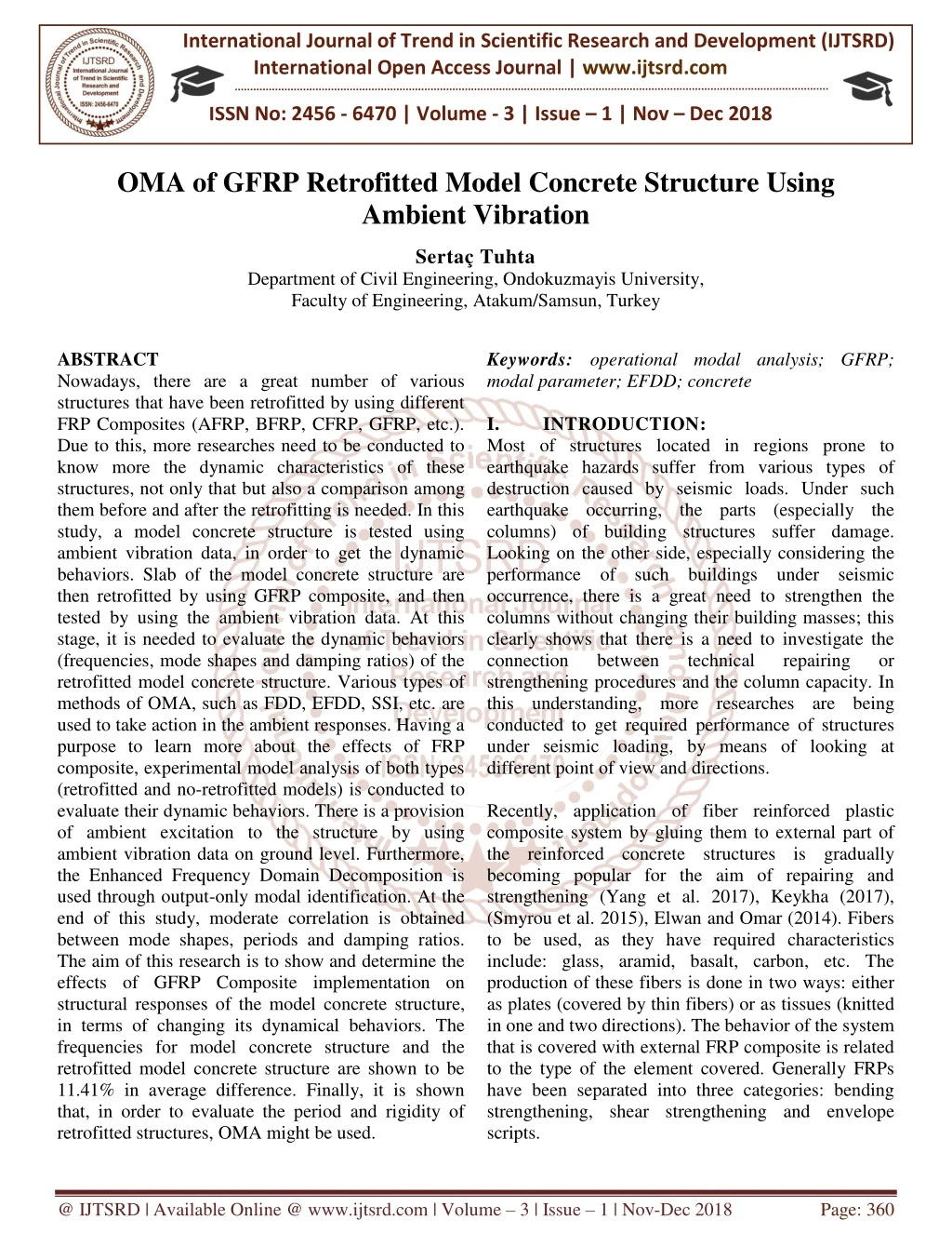
Nowadays, there are a great number of various structures that have been retrofitted by using different FRP Composites AFRP, BFRP, CFRP, GFRP, etc. . Due to this, more researches need to be conducted to know more the dynamic characteristics of these structures, not only that but also a comparison among them before and after the retrofitting is needed. In this study, a model concrete structure is tested using ambient vibration data, in order to get the dynamic behaviors. Slab of the model concrete structure are then retrofitted by using GFRP composite, and then tested by using the ambient vibration data. At this stage, it is needed to evaluate the dynamic behaviors frequencies, mode shapes and damping ratios of the retrofitted model concrete structure. Various types of methods of OMA, such as FDD, EFDD, SSI, etc. are used to take action in the ambient responses. Having a purpose to learn more about the effects of FRP composite, experimental model analysis of both types retrofitted and no retrofitted models is conducted to evaluate their dynamic behaviors. There is a provision of ambient excitation to the structure by using ambient vibration data on ground level. Furthermore, the Enhanced Frequency Domain Decomposition is used through output only modal identification. At the end of this study, moderate correlation is obtained between mode shapes, periods and damping ratios. The aim of this research is to show and determine the effects of GFRP Composite implementation on structural responses of the model concrete structure, in terms of changing its dynamical behaviors. The frequencies for model concrete structure and the retrofitted model concrete structure are shown to be 11.41 in average difference. Finally, it is shown that, in order to evaluate the period and rigidity of retrofitted structures, OMA might be used. Sertau00c3u00a7 Tuhta "OMA of GFRP Retrofitted Model Concrete Structure Using Ambient Vibration" Published in International Journal of Trend in Scientific Research and Development (ijtsrd), ISSN: 2456-6470, Volume-3 | Issue-1 , December 2018, URL: https://www.ijtsrd.com/papers/ijtsrd18979.pdf Paper URL: http://www.ijtsrd.com/engineering/civil-engineering/18979/oma-of-gfrp-retrofitted-model-concrete-structure-using-ambient-vibration/sertau00c3u00a7-tuhta<br>

E N D
International Journal of Trend in Scientific Research and Development (IJTSRD) International Open Access Journal | www.ijtsrd.com ISSN No: 2456 - 6470 | Volume - 3 | Issue – 1 | Nov – Dec 2018 OMA of GFRP Retrofitted Model Concrete Structure Using Ambient Vibration Sertaç Tuhta Department of Civil Engineering, Ondokuzmayis University, Faculty of Engineering, Atakum/Samsun, Turkey Keywords: operational modal analysis; GFRP; modal parameter; EFDD; concrete I. INTRODUCTION: Most of structures located in regions prone to earthquake hazards suffer from various types of destruction caused by seismic loads. Under such earthquake occurring, the parts (especially the columns) of building structures suffer damage. Looking on the other side, especially considering the performance of such buildings under seismic occurrence, there is a great need to strengthen the columns without changing their building masses; this clearly shows that there is a need to investigate the connection between technical strengthening procedures and the column capacity. In this understanding, more researches are being conducted to get required performance of structures under seismic loading, by means of looking at different point of view and directions. Recently, application of fiber reinforced plastic composite system by gluing them to external part of the reinforced concrete structures is gradually becoming popular for the aim of repairing and strengthening (Yang et al. 2017), Keykha (2017), (Smyrou et al. 2015), Elwan and Omar (2014). Fibers to be used, as they have required characteristics include: glass, aramid, basalt, carbon, etc. The production of these fibers is done in two ways: either as plates (covered by thin fibers) or as tissues (knitted in one and two directions). The behavior of the system that is covered with external FRP composite is related to the type of the element covered. Generally FRPs have been separated into three categories: bending strengthening, shear strengthening and envelope scripts. ABSTRACT Nowadays, there are a great number of various structures that have been retrofitted by using different FRP Composites (AFRP, BFRP, CFRP, GFRP, etc.). Due to this, more researches need to be conducted to know more the dynamic characteristics of these structures, not only that but also a comparison among them before and after the retrofitting is needed. In this study, a model concrete structure is tested using ambient vibration data, in order to get the dynamic behaviors. Slab of the model concrete structure are then retrofitted by using GFRP composite, and then tested by using the ambient vibration data. At this stage, it is needed to evaluate the dynamic behaviors (frequencies, mode shapes and damping ratios) of the retrofitted model concrete structure. Various types of methods of OMA, such as FDD, EFDD, SSI, etc. are used to take action in the ambient responses. Having a purpose to learn more about the effects of FRP composite, experimental model analysis of both types (retrofitted and no-retrofitted models) is conducted to evaluate their dynamic behaviors. There is a provision of ambient excitation to the structure by using ambient vibration data on ground level. Furthermore, the Enhanced Frequency Domain Decomposition is used through output-only modal identification. At the end of this study, moderate correlation is obtained between mode shapes, periods and damping ratios. The aim of this research is to show and determine the effects of GFRP Composite implementation on structural responses of the model concrete structure, in terms of changing its dynamical behaviors. The frequencies for model concrete structure and the retrofitted model concrete structure are shown to be 11.41% in average difference. Finally, it is shown that, in order to evaluate the period and rigidity of retrofitted structures, OMA might be used. repairing or @ IJTSRD | Available Online @ www.ijtsrd.com | Volume – 3 | Issue – 1 | Nov-Dec 2018 Page: 360
International Journal of Trend in Scientific Research and Development (IJTSRD) ISSN: 2456-6470 In order to strengthen reinforced concrete structures, the prevention of severe bending and shearing is realized by covering beams by FRP composite. Increasing the resistance and ductility of the system under lateral seismic loads the main goal of this covering. Li and Sung in (2003) they had presented lot of analytical and experimental tests on benchmark and on reinforced concrete damaged circular bridge column. In the benchmark column is a 40% scale reinforced concrete circular bridge column damaged because of shear failure during a cyclic-loading test. Then the column repaired by epoxy and non- shrinkage mortar and rehabilitated by (CFRP) carbon fiber reinforced plastic after the cyclic-loading test. Experimental result could be predicted accurately by the analytical lateral force-displacement relationship of the bridge columns, especially in the nonlinear regions. In their study, for circular reinforced concrete bridge column, the result has been reached so that for a true repair; a change of the shear-failure mode of bridge column to the bending-failure refraction occurs, in other words this increases the seismic performance the analytical and experimental by (Montoya et al. 2004) are fitted with the numerical results of nonlinear finite element evaluation for the behavior of steel and FRP contained concrete columns which formulated and implemented. The performance of reinforced concrete column which was covered with carbon FRP was determined under uniaxial compression load Cole (2001). When Strengthened with CF-130 carbon fiber laminates, the experimental result for five circular columns and three rectangular columns were tested in pure compression shows that ±45 degrees CFRP laminate can effectively be used to provide columns ductility performance. When the main goal is to boost the load capacity, a unidirectional FRP laminate might be more effective according to Paretti and Nanni (2002). According to Parvin and Wang study (2002), they talk over the effect of strain gradient and FRP thickness on square concrete columns reinforced with FRP wraps. The results for nine square concrete columns were tested under eccentric load and two different levels of eccentricity. it was shown that the chosen eccentricity values were small enough to produce any longitudinal tension in the wrap. The aim of this study is to evaluate the performance of reinforced concrete column, which has rectangular cross-section, under axial static compression load by using analytical, numerical and experimental evaluations and also to increase the source of statistics with a comparison target on this field. It has been shown that beams of existing structures suffer too much during seismic loading. Reinforced concrete rectangular cross-section column was used to evaluate their performance under axial static compression load by using analytical, numerical and experimental evaluations and also to increase the source of statistics with a comparison target on this field. It has been shown that beams of existing structures suffer too much during seismic loading. analytical and experimental results by testing “T” cross section reinforced concrete beam, the beams strengthen with carbon fiber reinforced plastic composite (CFRP), the results show that tension increased at the negative approximately 40% according to (Namboorimadathil et al. 2002) study. The distance from support to CFRP origin and effect of cross-section beam and its behavior have been studied in (Ahmed et al. 2001) study, when it was strengthened with CFRP composite at the tensile region of reinforced concrete beam. Computation formula has been composed related to experimental results, to guess the design load that is equal to the limit position of beam. In this examination original shear stress and slight effect have been taken into consideration. The performance of partial bridge strengthened by CFRP composite has been tested in (Ramos et al. 2004) study. On partial scaled and full-scaled specimen, partial beams experiments were conducted. Bond scaled experiment has been shown as alternative for characterizing repair and strengthening the partial structures with CFRP composite. For pre-stressed three reinforced concrete girder bridge that suffered damage which repair- strengthening with CFRP composite. Experimental results before and after repairing was presented by (Klaiber et al. 2003) study, the results shown that using of CFRP is productive. The girder bending displacements have been decreased more than 20% when CFRP was used. When Strengthened with CF- 130 carbon fiber laminates, fifteen rectangular beams were tested in pure compression. The experimental result shows that CFRP laminate can effectively be used to provide beams ductility performance. The effect of FRP wrapping number to the maximum axial capacity has been evaluated Kasimzade and Tuhta (2012). As already known, forced (shaker, impact, pull back or quick release tests) and ambient vibration techniques are available for vibration testing of large structures. Force vibration methods are tougher and generally not cheap compared to ambient vibration tests. So the later (ambient vibration testing, also moment region @ IJTSRD | Available Online @ www.ijtsrd.com | Volume – 3 | Issue – 1 | Nov-Dec 2018 Page: 361
International Journal of Trend in Scientific Research and Development (IJTSRD) ISSN: 2456-6470 called Operational Modal Analysis) is the most economical non-destructive testing method to acquire vibration data from large civil engineering structures for Output-Only Model Identification. General characteristics of structural response (appropriate frequency, displacement, velocity, and acceleration rungs), suggested measuring quantity (such as velocity or acceleration); depend on the type of vibrations (Traffic, Acoustic, Machinery inside, Earthquakes, Wind…) that are given in Vibration of Buildings (1990). These structure response characteristics give a general idea of the preferred quantity to be measured. A few studies on the analysis of ambient vibration measurements of buildings from 1982 until 1996 were discussed in Ventura and Schuster (1996). Last ten years Output-Only Model Identification studies of buildings are given in appropriate references as structural vibration solutions. For the modal updating of the structure it is necessary to estimate sensitivity of reaction of examined system to the change of parameters of a building. The work of Kasimzade (2006) on system identification is about the process of developing or improving representation of a physical system. The experimental data are investigated in HO and Kalman (1966), Kalman (1960), Ibrahim and Miculcik (1977), Ibrahim (1977), Bendat (1998), Ljung (1999), Juang (1994), Van Overschee and De Moor (1996), and system identification applications in civil engineering structures are presented in works of Trifunac (1972), Turker (2014), (Altunisik et al. 2010), (Brincker et al. 2000), Roeck (2003), Peeters (2000), (Cunha et al. 2005), Wenzel and Pichler (2005), Kasimzade and Tuhta (2007a, b), (2009), (Ni et al. 2015), Lam and Yang (2015), Papadimitriou and Papadioti (2013), Au and Zhang (2016), Zhang and Au (2016), (Zhang et al. 2016), (Ni et al. 2017). Extracting system physical parameters from identified state space representation was investigated in the following references: Alvin and Park (1994), Balmes (1997), (Juanget al.1988), Juang and Pappa (1985), (Lus et al. 2003), (Phan et al. 2003), Sestieri and Ibrahim (1994), (Tseng et al. 1994). The solution for algebraic Riccati equation matrix and orthogonality projection, which is more intensively and inevitably identification, was deeply investigated in works of Aliev (1998). In engineering structures there are three types of identification that are used: modal parameter identification; structural-modal identification and control-model methods. In the frequency domain the identification is based on the singular value decomposition of the spectral density matrix and it is denoted as Frequency Domain Decomposition (FDD) and its further development Enhanced Decomposition (EFDD). In the time domain there are three different implementations of the Stochastic Subspace Identification (SSI) technique: Unweighted Principal Component (UPC); Principal component (PC); Canonical Variety Analysis (CVA) which were used for the modal updating of the structure Friswell and Mottershead (1995), Marwala (2010). It is required to estimate the sensitivity of reaction of examined system to change of random or fuzzy parameters of a structure. Investigated measurement noise perturbation influences to the identified system modal and physical measurement noise border, for which identified system parameters are acceptable for validation of finite element model identification is realized by observer Kalman filter (Juang et al. 1993) and Subspace Overschee with De Moor (1996) algorithms. For some specialties, the observer gain coincides with the Kalman gain. Stochastic state-space model of the structure is simulated by Monte-Carlo method. The dangers and difficulties of shaking the structures with forced vibrations, the large size of the vibrators, the possibility of destruction of the structure, the disruption of daily life, the cost of the experiment is taken into consideration, operational modal analysis are emphasized according to the experimental modal analysis and therefore the operational method is more widely used. Operational modal analysis technique it has important advantages such as the full scale of the work being done, no damage, no external load impact on the structure. For this purpose, experimental modal analysis of a model concrete structure for dynamic characteristics was evaluated. Then, retrofitted model concrete structure for dynamic characteristics was also evaluated. Ambient excitation was provided ambient vibration data on ground level. The Enhanced Frequency Domain Decomposition is used for the output-only modal identification. II. MODAL PARAMETER EXTRACTIONS As it is already known, the ambient modal identification (FDD) is an extension of the Basic Frequency Domain (BFD) technique or called the Peak-Picking technique. This method uses the fact that modes can be estimated from the spectral Frequency Domain parameters, estimated of examined System a mathematical the advantages of used in system parameter identification @ IJTSRD | Available Online @ www.ijtsrd.com | Volume – 3 | Issue – 1 | Nov-Dec 2018 Page: 362
International Journal of Trend in Scientific Research and Development (IJTSRD) ISSN: 2456-6470 densities calculated, in the case of a white noise input, and a lightly damped structure. It is a non-parametric technique to determine the modal parameters directly from signal processing. The FDD technique estimates the modes using a Singular Value Decomposition (SVD) of each of the measurement data sets. This decomposition corresponds to a Single Degree of Freedom (SDOF) identification of the measured system for each singular value (Brincker et al. 2000). The Enhanced Frequency Domain Decomposition technique is an extension to Frequency Domain Decomposition (FDD) technique. This technique is a simple technique that is extremely basic for use. In this technique, modes are easily picked locating the peaks in Singular Value Decomposition (SVD) plots calculated from the spectral density spectra of the responses. FDD technique is based on using a single frequency line from the Fast Fourier Transform analysis (FFT), the accuracy of the estimated natural frequency based on the FFT resolution and no modal damping is calculated. On the other hand, EFDD technique gives an advanced estimation of both the natural frequencies and the mode shapes, including the damping ratios (Jacobsen et al. 2006). In EFDD technique, the single degree of freedom (SDOF) Power Spectral Density (PSD) function, identified as a peak of resonance, is taken back to the time domain using the Inverse Discrete Fourier Transform (IDFT). The natural frequency is acquired by defining the number of zero crossing as a function of time, and the damping by the logarithmic decrement of the correspondent single degree of freedom (SDOF) normalized auto correlation function Peeters (2000). In this research, modal parameter identification is implemented by the Enhanced Frequency Domain Decomposition. The relationship between the input (x(t))and responses (y(t)) in the EFDD technique can be written as, [Gyy(jω)]=[H(jω)]*[Gxx(jω)][H(jω)]T(1) Where Gxx(jω) is the rxr Power Spectral Density (PSD) matrix of the input. Gyy(jω)is the mxmPower Spectral Density (PSD) matrix of the output, H(jω)is the mxr Frequency Response Function (FRF) matrix, * and superscript Tdenote complex conjugate and transpose, respectively. The FRF can be reduced to a pole/residue form as follows: [Y(ω)] [X(ω)]=∑ Where n is the number of modes λk is the pole and, Rk is the residue. Then Eq. (1) becomes as: ???(jω)=∑ ∑ ?=1 ?=1 [??]∗ ??-?? [??] ??-??+ [??]∗ ??-?? ? ? (3) [ ∗] ? ̅ [??] ??-??+ (3) ???(jω)[ ∗] Where ? the singular values, superscript is ? denotes complex conjugate and transpose. Multiplying the two partial fraction factors and making use of the Heaviside partial fraction theorem, after some mathematical manipulations, the output PSD can be reduced to a pole/residue form as fallows; [Ak] jω-λk+ Where Ak is the ? th residue matrix of the output PSD. In the EFDD identification, the first step is to estimate the PSD matrix. The estimation of the output PSD known at discrete frequencies is then decomposed by taking the SVD (singular value decomposition) of the matrix; Gyy(jωi)=UiSiUi Where the matrix Ui=[ui1,ui2,…,uim] is a unitary matrix holding the singular vectors uij and sij G is a diagonal matrix holding the scalar singular values. The first singular vector uij is an estimation of the mode shape. PSD function is identified around the peak by comparing the mode shape estimation uij with the singular vectors for the frequency lines around the peak. From the piece of the SDOF density function obtained around the peak of the PSD, the natural frequency and the damping can then be obtained. III. DESCRIPTION OF MODEL CONCRETE STRUCTURE Model concrete structure is 55 cm height. Thickness of elements (shear walls and slab) is 5.5 cm. C20 concrete is used in construction. The structure dimensions are shown in Fig. 2. [Ak]* jω-λk [Bk] -jω-λk(4) n k=1 [Gyy(jω)]=∑ *+ ? ̅(5) [Rk]* jω-λk [Rk] jω-λk+ m k=1 (2) [H(ω)]= Fig. 1 Illustration of model concrete structure * @ IJTSRD | Available Online @ www.ijtsrd.com | Volume – 3 | Issue – 1 | Nov-Dec 2018 Page: 363
International Journal of Trend in Scientific Research and Development (IJTSRD) ISSN: 2456-6470 Fig. 2 Illustration of the model concrete structure’s dimensions IV. EXPERIMENTAL MODAL ANALYSIS OF MODEL CONCRETE STRUCTURE The ambient excitation is provided by using recorded micro tremor data on accelerometers (triaxial) are used to measure ambient vibrations, one of them is allocated as reference sensor, which is always located in the slab (shown by the red arrows in Fig. 3a, b). Two accelerometers are used as roving sensors (shown by the black arrows in Fig. 3a, b). The response was measured in two data sets (Fig. 3 a, b). For two data sets, 2 and 4 degree of freedom records are used respectively (Fig. 3 a, b). Every data set (Fig. 3 a, b) is measured within 100 minutes. The selected measurement points and directions are shown in Fig. 3 a, b. The ambient excitation is provided by using recorded micro tremor data on ground level (Fig. 4 a, b). ground level. Two b) Second setup Fig. 3 Accelerometers location of experimental model in the 3D view The data acquisition computer provides the ambient vibration records. During measurements, the data files from the previous setup are transferred to the computer for data analysis by using a software package. However, in case there is a display of unexpected signal drifts or unwanted noise or corrupted for some unknown reasons, the data set must be discarded and measurements be repeated. Fig. 4 Ambient vibrations recorded by the seismometer Before measurements the cable used to connect the sensors to the data acquisition equipment must be laid out. Following each measurement, the roving sensors are systematically located from floor to floor until the test is completed (Fig. 3 a, b). The equipment used for the measurement includes accelerometers (with both x and y directional measurements) and güralp systems seismometer and matlab data acquisition toolbox (wincon). For modal parameter estimation from the ambient vibration data, a) First setup three sensebox @ IJTSRD | Available Online @ www.ijtsrd.com | Volume – 3 | Issue – 1 | Nov-Dec 2018 Page: 364
International Journal of Trend in Scientific Research and Development (IJTSRD) ISSN: 2456-6470 the operational modal analysis (OMA) software ARTeMIS Extractor (1999) is used. Fig. 5 Singular values of spectral density matrices (model concrete structure) The Eigen frequencies are found as the peaks of non- parametric spectrum estimates when the simple peak- picking method (PPM) is used. This frequency selection procedure becomes a subjective task in case of noisy test data, weakly excited modes and relatively close Eigen frequencies. Also for damping ratio estimation, the related half-power bandwidth method is not favorable. This why the most popular and useful algorithm to use is Frequency domain one, because of its convenience and operating speed. Singular values of spectral density matrices, attained from vibration data using PP (Peak Picking) technique are shown in Fig. 5. Natural frequencies acquired from all measurement setup are given in Table 2. The first five mode shapes extracted from experimental modal analyses are given in Fig. 6. When all measurements are examined, it can be seen that a best accordance is found between experimental mode shapes. In addition, when both setup sets are experimentally identified modal parameters are checked with each other, it can be seen that there is a best agreement between the mode shapes in the experimental modal analyses. Table 1 Experimental modal analysis result at the model concrete structure Mode number Frequency (Hz) Modal damping ratio (ξ) (%) 1stMode Shape (f=11.82 Hz, ξ=0.378) 2nd Mode Shape (f=12.38 Hz, ξ=0.361) 1 2 3 4 5 11.82 12.38 13.01 13.62 14.04 0.378 0.361 0.344 0.328 0.319 3rdMode Shape (f=13.01 Hz, ξ=0.344) @ IJTSRD | Available Online @ www.ijtsrd.com | Volume – 3 | Issue – 1 | Nov-Dec 2018 Page: 365
International Journal of Trend in Scientific Research and Development (IJTSRD) ISSN: 2456-6470 Fig. 7 GFRP composite and using details The steps to pass through during retrofitting are shown below in details: A thin coat of putty is applied (Fig. 7) to the slab, approximately 1hour of curing in order to prepare a surface for application of GFRP composite. Next step, bottom surface of slab is covered with GFRP composites. After these setups, ambient vibration tests are followed by curing to obtain experimental dynamic characteristics similar to previously used properties in order to obtain comparative measurements. SVSDM are shown in Fig. 8. Table 3 shows the identified natural frequencies and modal damping ratios. It is clear that using GFRP composites seems to be very effective for strengthening concrete members along with increasing stiffness; this research aims to determine how GFRP composite implementation affects structural response of model concrete structure by changing of dynamic characteristics. 4thMode Shape (f=7.770 Hz, ξ=0.551) 5thMode Shape (f=8.987 Hz, ξ=0.670) Fig. 6 experimentally identified mode shapes of model EXPERIMENTAL MODAL ANALYSIS OF RETROFITTED CONCRETE STRUCTURE In the case of retrofitted beams, the following are studies made on it to check and examine the efficiency of using unidirectional GFRP composite: slab of the model concrete structure is retrofitted with one layer GFRP composite. The Unidirectional GFRP composite and its components YKS Fiber is product of YKS Corporation (Fig. 7). The properties of the dry carbon fiber composite are: E=1.350E11 N/m2, Poisson ratio μ=0.3, mass per unit volume ρ=15696 N/m3, thickness=0.000152 m. V. Fig. 8 Singular values of spectral density matrices (retrofitted model concrete structure) MODEL 1stMode Shape (f=13.45 Hz, ξ=0.332) @ IJTSRD | Available Online @ www.ijtsrd.com | Volume – 3 | Issue – 1 | Nov-Dec 2018 Page: 366
International Journal of Trend in Scientific Research and Development (IJTSRD) ISSN: 2456-6470 2nd Mode Shape (f=14.04 Hz, ξ=0.319) 5thMode Shape (f=15.23 Hz, ξ=0.294) Fig. 9 experimentally identified mode shapes of retrofitted model concrete structure Table 2 Experimental modal analysis result at the retrofitted model concrete structure Mode number Frequency (Hz) Modal damping ratio (ξ) (%) 1 2 3 4 5 13.45 14.04 14.60 14.87 15.23 0.332 0.319 0.306 0.301 0.294 Table 3 Comparison of existing and retrofitted modal analysis results Mode number Frequency (Hz)-E Frequency (Hz)-R Difference (%) E: Existing model R: Retrofitted model VI. CONCLUSIONS In this research, the conducted experimental modal analysis of existing model concrete structure and GFRP composite retrofitted model concrete structure. Comparing the result of study, the followings are noticed: ➢From the ambient vibration test, the first five natural frequencies attained experimentally, range between 11 and 16 Hz. 1 2 3 4 5 3rdMode Shape (f=14.60 Hz, ξ=0.306) 11.82 12.38 13.01 13.62 14.04 13.45 14.04 14.60 14.87 15.23 13.79 13.40 12.22 9.17 8.47 were both 4thMode Shape (f=14.87 Hz, ξ=0.301) @ IJTSRD | Available Online @ www.ijtsrd.com | Volume – 3 | Issue – 1 | Nov-Dec 2018 Page: 367
International Journal of Trend in Scientific Research and Development (IJTSRD) ISSN: 2456-6470 ➢The modal frequency difference lies in the interval of 8.47%-13.79% for Existing and retrofitted case and it provides the increase of frame structure stiffness about 11.41%; for the retrofitted model, using GFRP applied to slab only. ➢It can be generally stated that ambient vibration testing can be safely used to observe the retrofitting effects on the response of concrete structures. The results of dynamic identification can be used in damage detection and in the developing and updating of the finite element models of the concrete structures. ➢The conclusion of the experiment strongly suggests that the retrofitting should be very efficient to increase stiffness and natural frequencies. ➢In this study, it is shown that OMA may be used to evaluate the period and rigidity of the retrofitted structures. REFERENCES 1.Ahmed, O., Van Gemert, D. and Vandewalle, L. (2001), “Improved model for plate-end shear of CFRP strengthened RC beams”, Cement and Concrete Composites, 23(1), 3-19. 2.Aliev, F. A. and Larin, V. B. (1998), Optimization of Linear Control Systems: Analytical Methods and Computational Algorithms, CRC Press. 3.Altunisik, A. C., Bayraktar, A., Sevim, B., Kartal, M. E. and Adanur, S. (2010), “Finite element model updating of an arch type steel laboratory bridge model using semi-rigid connection”, Steel and Composite Structures, 10(6), 541-561. 4.Alvin, K. F. and Park, K. C. (1994), “Second- order structural identification procedure via state- space-based system identification”, AIAA Journal, 32(2), 397-406. 5.ANSI S2.47-1990 Vibration Guidelines for the measurement of vibrations and evaluation of their effects on buildings. 6.ARTeMIS Extractor, Solutions, Aalborg, Denmark, 1999. 7.Au, S. K. and Zhang, F. L. (2016), “Fundamental two-stage formulation for Bayesian system identification, Part I: General theory”, Mechanical Systems and Signal Processing, 66, 31-42. 8.Balmes, E. (1997), “New results on the identification of normal modes from experimental complex modes”, Mechanical Systems and Signal Processing, 11(2), 229-243. 9.Bendat, J. S. (1998), Nonlinear Systems Techniques and Applications, Wiley. 10.Brincker, R., Zhang, L. and Andersen, P. (2000), “Modal identification from ambient responses using frequency domain Proceedings of the 18th International Modal Analysis Conference (IMAC),San Antonio, Texas, USA, February. 11.Buyukozturk, O. and Hearing, B. (1998), “Failure behavior of precracked concrete beams retrofitted with FRP”, Journal Construction, 2(3), 138-144. 12.Cunha, A., Caetano, E., Magalhaes, F. and Moutinho, C. (2005), “From input-output to output-only modal engineering structures”, Operational Modal (IOMAC), Copenhagen, Denmark, April. 13.Dong, Y., Zhao, M. and Ansari, F. (2002), “Failure characteristics of reinforced concrete beams repaired with CFRP composites”, Third International Conference on Composites in Infrastructure (ICCI'02), Francisco, California, USA, June. 14.Friswell, M. and Mottershead, J. E. (1995), Finite Element Model Updating In Structural Dynamics, Springer Science-Business Media. 15.GangaRao, H. V. and Vijay, P. V. (1998), “Bending behavior of concrete beams wrapped with carbon fabric”, Journal of Structural Engineering, 124(1), 3-10. 16.HO, Β. and Kalman, R. E. (1966), “Effective construction of linear state-variable models from input/output Automatisierungstechnik, 14(1-12), 545-548. 17.Ibrahim, S. R. (1977), “Random decrement technique for modal identification of structures”, Journal of Spacecraft and Rockets, 14(11), 696- 700. 18.Ibrahim, S.R. and Miculcik, E.C. (1977), “A method for the direct identification of vibration parameters from the free response”, The Shock and Vibration Bulletin, 47(4), 183-194. 19.Jacobsen, N. J., Andersen, P., and Brincker, R. (2006), “Using enhanced frequency domain decomposition”, of Composites for identification 1st Analysis of civil International Conference at- functions”, of buildings- Structural Vibration @ IJTSRD | Available Online @ www.ijtsrd.com | Volume – 3 | Issue – 1 | Nov-Dec 2018 Page: 368
International Journal of Trend in Scientific Research and Development (IJTSRD) ISSN: 2456-6470 decomposition as a robust technique to harmonic excitation in operational International Conference on Noise and Vibration Engineering (ISMA),Leuven, September. 20.Juang, J. N. (1994), Identification, Prentice Hall. 21.Juang, J. N. and Pappa, R. S. (1985), “An eigensystem realization algorithm for modal parameter identification and model reduction”, Journal of Guidance, Control, And Dynamics, 8(5), 620-627. 22.Juang, J. N., Cooper, J. E. and Wright, J. R. (1988), “An eigensystem realization algorithm using data correlations (ERA/DC) for modal parameter identification”, Control-Theory and Advanced Technology, 4(1), 5-14. 23.Juang, J. N., Phan, M., Horta, L. G. and Longman, R. W. (1993), “Identification of observer/kalman filter markov parameters-theory and experiments”, Journal of Guidance, Control, and Dynamics, 16(2), 320-329. 24.Kakaletsis, D. J. experimental assessment of seismic rehabilitation with CFRP strips and sheets on RC frames”, Earthquakes and Structures, 10(3), 613-628. 25.Kalman, R. E. (1960), “A new approach to linear filtering and prediction problems”, Journal of Basic Engineering, 82(1), 35-45. 26.Kasimzade, A. A. (2006), “Coupling of the control system and the system identification toolboxes with application dynamics”, International Control Conference (ICC2006), Glasgow, Scotland, UK, September. 27.Kasimzade, A. A. and Tuhta S. (2007), “Ambient vibration analysis of steel structure”, Experimental Vibration Analysis Structures (EVACES’07), October. 28.Kasimzade, A. A. and Tuhta S. (2007), “Particularities of monitoring, identification, model updating hierarchy in vibration analysis of structures”, Experimental Vibration Analysis Structures (EVACES’07), October. 29.Kasimzade, A. A. and Tuhta S. (2009), “Optimal estimation the building system characteristics for modal Operational (IOMAC), Porto Novo, Ancona, Italy, May. 30.Klaiber, F. W., Wipf, T. J. and Kempers, B. J. (2003), “Repair of damaged prestressed concrete bridges using CFRP”, Transportation Research Symposium, Ames, Iowa, USA, August. 31.Lam, H. F. and Yang, J. (2015), “Bayesian structural damage detection of steel towers using measured modal parameters”, Earthquakes and Structures, 8(4), 935-956. 32.Li, Y. F. and Sung, Y. Y. (2003), “Seismic repair and rehabilitation of a shear-failure damaged circular bridge column using carbon fiber reinforced plastic jacketing”, Canadian Journal of Civil Engineering, 30(5), 819-829. 33.Liang, J., Yu, D., Wang, J. and Yi, P. (2016). “Mechanical properties of concrete beams reinforced with CFRP prestressed prisms under reverse cyclic loading”, Structures, 11(2), 315-326. 34.Ljung, L. (1999), System Identification: Theory for the User, Prentice Hall. 35.Lus, H., De Angelis, M., Betti, R. and Longman, R. W. (2003), “Constructing second-order models of mechanical systems from identified state space realizations. Part I: Theoretical discussions”, Journal of Engineering Mechanics, 129(5), 477- 488. 36.Marwala, T. (2010), Finite Element Model Updating Using Computational Techniques: Applications to Structural Dynamics, Springer Science-Business Media. 37.Mirmiran, A., Shahawy, M., Nanni, A., and Karbhari, V. (2004). Bonded repair and retrofit of concrete structures using FRP composites: Recommended construction specifications and process control manual (No. Project 10-59A FY'01). 38.Namboorimadathil, S. M., Tumialan, J. G. and Nanni, A. (2002), “Behavior of RC T beams strengthened in the negative moment region with CFRP laminates”, Third International Conference on Composites in Infrastructure (ICCI'02), Francisco, California, USA, June. 39.Ni, Y. Q., Zhang, F. L., Xia, Y. X. and Au, S. K. (2015), “Operational modal analysis of a long- identification”, Modal 3rd International Conference Analysis modal analysis”, Belgium, Applied System Mid-Continental Earthquakes and (2016), “Comparative in structural Intelligence of Civil Porto, Engineering Portugal, experimental of Civil Porto, Engineering Portugal, @ IJTSRD | Available Online @ www.ijtsrd.com | Volume – 3 | Issue – 1 | Nov-Dec 2018 Page: 369
International Journal of Trend in Scientific Research and Development (IJTSRD) ISSN: 2456-6470 50.Trifunac, M. D. (1972), “Comparisons between ambient and forced vibration experiments”, Earthquake Engineering and Structural Dynamics, 1(2), 133-150. 51.Tseng, D. H., Longman, R. W. and Juang, J. N. (1994), “Identification of the structure of the damping matrix in second order mechanical systems”, Spaceflight Mechanics, 167-190. 52.Tseng, D. H., Longman, R. W. and Juang, J. N. (1994), “Identification nongyroscopic second order mechanical systems including repeated root problems”, Spaceflight Mechanics, 145-165. 53.Turker, T. (2014). “Structural evaluation of Aspendos (Belkis) masonry bridge”, Structural Engineering and Mechanics, 50(4), 419-439. 54.Van Overschee, P. and De Moor, B. L. (1996), Subspace Identification for Linear Systems: Theory-Implementation-Applications, Science -Business Media. 55.Ventura, C. E. and Schuster, N. D. (1996), “Structural dynamic properties of a reinforced concrete high-rise building during construction”, Canadian Journal of Civil Engineering, 23(4), 950-972. 56.Wenzel, H. and Pichler, D. (2005), Ambient Vibration Monitoring, John Wiley & Sons. 57.Zhang, F. L. and Au, S. K. (2016), “Fundamental two-stage formulation for Bayesian system identification, Part II: Application to ambient vibration data”, Mechanical Systems and Signal Processing, 66, 43-61. 58.Zhang, F. L., Ni, Y. C., Au, S. K. and Lam, H. F. (2016), “Fast Bayesian approach for modal identification using free vibration data, Part I- Most probable value”, Mechanical Systems and Signal Processing, 70, 209-220. span suspension bridge under different earthquake events”, Earthquakes and Structures, 8(4), 859- 887. 40.Ni, Y., Lu, X. and Lu, W. (2017), “Operational modal analysis of a high-rise multi-function building with dampers by a Bayesian approach”, Mechanical Systems and Signal Processing, 86, 286-307. 41.Papadimitriou, C. and Papadioti, D. C. (2013), “Component mode synthesis techniques for finite element model updating”, Structures, 126, 15-28. 42.Peeters, B. (2000), “System identification and damage detection in civil engineering”, Ph.D. Dissertation, KatholiekeUniversiteit Leuven, Belgium. 43.Phan, M. Q., Longman, R. W., Lee, S. C. and Lee, J. W. (2003), “System identification from multiple-trial data corrupted by non-repeating periodic disturbances”, International Journal of Applied Mathematics and Computer Science, 13(2), 185-192. 44.Rahimi, H. and Hutchinson, A. (2001), “Concrete beams strengthened with externally bonded FRP plates”, Journal of Composites for Construction, 5(1), 44-56. 45.Ramos, G., Casas, J. R. and Alarcón, A. (2004), “Repair and strengthening of segmental bridges using carbon fibers”, Engineering Structures, 26(5), 609-618. 46.Roeck, G. D. (2003), “The state‐of‐the‐art of damage detection by vibration monitoring: the SIMCES experience”, Journal of Structural Control, 10(2), 127-134. 47.Sestieri, A. and Ibrahim, S. R. (1994), “Analysis of errors and approximations in the use of modal coordinates”, Journal of Sound and Vibration, 177(2), 145-157. 48.Smyrou, E., Karantzikis, M. and Bal, İ. E. (2015), “FRP versus traditional strengthening on a typical mid-rise Turkish RC building”, Earthquakes and Structures, 9(5), 1069-1089. 49.Thomsen, H., Spacone, E., Limkatanyu, S. and Camata, G. (2004), “Failure mode analyses of reinforced concrete beams strengthened in flexure with externally bonded polymers”, Journal Construction, 8(2), 123-131. of gyroscopic and Computers & Leuven, Springer fiber-reinforced Composites of for @ IJTSRD | Available Online @ www.ijtsrd.com | Volume – 3 | Issue – 1 | Nov-Dec 2018 Page: 370