Download
1 / 5
50 likes | 52 Views
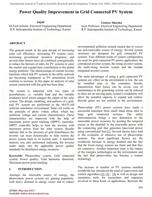
The solar panel is one of the most sought after methods to produce electrical energy for domestic purposes. Solar PV T systems converts solar irradiation into thermal and electrical energy. Module is made of Poly c Si material. This experiment aims at analysing the comparative performance of hybrid solar PV T water collectors connected in series and parallel. It was conducted in Saranathan College of Engineering, Tiruchirapalli 12. It is located at latitude of 10.7560u00c2u00b0N and longitude of 78.6513u00c2u00b0E. The maximum temperature of water obtained was 42.8u00c2u00b0C and 40.8u00c2u00b0C respectively in series and parallel. Overall the parallel connected PV T system's performance is 12.12 higher than the series connected PV T system. S. Paramaguru | P. Sivakumar | M. Sridharan | Dr. T. Senthilkumar "Performance Improvement Analysis on PV/T Solar Water Collectors Connected in Series and Parallel" Published in International Journal of Trend in Scientific Research and Development (ijtsrd), ISSN: 2456-6470, Volume-2 | Issue-4 , June 2018, URL: https://www.ijtsrd.com/papers/ijtsrd14200.pdf Paper URL: http://www.ijtsrd.com/engineering/mechanical-engineering/14200/performance-improvement-analysis-on-pvt-solar-water-collectors-connected-in-series-and-parallel/s-paramaguru<br>

E N D
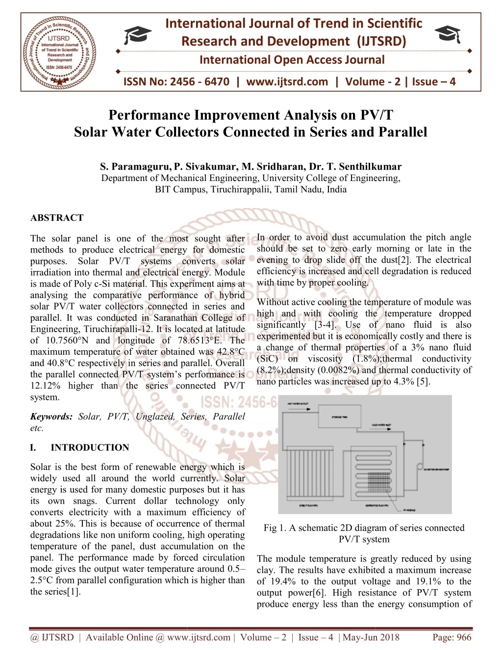
International Research Research and Development (IJTSRD) International Open Access Journal Performance Improvement Analysis on PV/T Solar Water Collectors Connected in Series and Parallel Solar Water Collectors Connected in Series and Parallel International Journal of Trend in Scientific Scientific (IJTSRD) International Open Access Journal ISSN No: 2456 ISSN No: 2456 - 6470 | www.ijtsrd.com | Volume 6470 | www.ijtsrd.com | Volume - 2 | Issue – 4 Performance Improvement Analysis on Solar Water Collectors Connected in Series and Parallel PV/T S. Paramaguru,P. Sivakumar Department of Mechanical Engineering BIT Campus, Tiruchirappalii, Tamil BIT Campus, Tiruchirappalii, Tamil Nadu, India kumar Sivakumar, M. Sridharan, Dr. T. Senthilk Department of Mechanical Engineering, University College of Engineering, Engineering, ABSTRACT The solar panel is one of the most sought after methods to produce electrical energy for domestic purposes. Solar PV/T systems converts solar irradiation into thermal and electrical energy. Module is made of Poly c-Si material. This experiment aims at analysing the comparative performance of hybrid solar PV/T water collectors connected in series and parallel. It was conducted in Saranathan College of Engineering, Tiruchirapalli-12. It is located at latitude of 10.7560°N and longitude of 78.6513°E. The maximum temperature of water obtained was 42.8°C and 40.8°C respectively in series and parallel. Overall the parallel connected PV/T system’s performance is 12.12% higher than the series connected PV/T system. In order to avoid dust accumulation the pitch angle should be set to zero early morning or late in the evening to drop slide off the dust[2]. The electrical In order to avoid dust accumulation the pitch angle should be set to zero early morning or late in the evening to drop slide off the dust[2]. The electrical efficiency is increased and cell degradation is reduced with time by proper cooling. The solar panel is one of the most sought after methods to produce electrical energy for domestic purposes. Solar PV/T systems converts solar nto thermal and electrical energy. Module Si material. This experiment aims at analysing the comparative performance of hybrid solar PV/T water collectors connected in series and parallel. It was conducted in Saranathan College of ell degradation is reduced Without active cooling the temperature of module was high and with cooling the temperature dropped significantly [3-4]. Use of nano fluid is also experimented but it is economically costly and there a change of thermal properties of a 3% nano fluid (SiC) on viscosity (1.8%);thermal conductivity (8.2%);density (0.0082%) and thermal conductivity of nano particles was increased up to 4.3% [5]. nano particles was increased up to 4.3% [5]. Without active cooling the temperature of module was high and with cooling the temperature dropped 4]. Use of nano fluid is also experimented but it is economically costly and there is a change of thermal properties of a 3% nano fluid (SiC) on viscosity (1.8%);thermal conductivity (8.2%);density (0.0082%) and thermal conductivity of 12. It is located at latitude of 10.7560°N and longitude of 78.6513°E. The maximum temperature of water obtained was 42.8°C and 40.8°C respectively in series and parallel. Overall the parallel connected PV/T system’s performance is 12% higher than the series connected PV/T Keywords: Solar, PV/T, Unglazed, Series, Parallel etc. Solar, PV/T, Unglazed, Series, Parallel I. INTRODUCTION Solar is the best form of renewable energy which is widely used all around the world currently. Solar energy is used for many domestic purposes but it has its own snags. Current dollar technology only converts electricity with a maximum efficiency of about 25%. This is because of occurrence of thermal degradations like non uniform cooling, high operating temperature of the panel, dust accumulation on the panel. The performance made by forced circulation mode gives the output water temperature around 0.5 2.5°C from parallel configuration which is higher than the series[1]. Solar is the best form of renewable energy which is widely used all around the world currently. Solar energy is used for many domestic purposes but it has its own snags. Current dollar technology only converts electricity with a maximum efficiency of 25%. This is because of occurrence of thermal degradations like non uniform cooling, high operating temperature of the panel, dust accumulation on the panel. The performance made by forced circulation mode gives the output water temperature around 0.5– °C from parallel configuration which is higher than Fig 1. A schematic 2D diagram of series connected Fig 1. A schematic 2D diagram of series connected PV/T system system The module temperature is greatly reduced by using clay. The results have exhibited a maximum increase of 19.4% to the output voltage and 19.1% to the output power[6]. High resistance of PV/T system The module temperature is greatly reduced by using clay. The results have exhibited a maximum increase of 19.4% to the output voltage and 19.1% to the output power[6]. High resistance of PV/T system produce energy less than the energy consumption o produce energy less than the energy consumption of @ IJTSRD | Available Online @ www.ijtsrd.com @ IJTSRD | Available Online @ www.ijtsrd.com | Volume – 2 | Issue – 4 | May-Jun Jun 2018 Page: 966
International Journal of Trend in Scientific Research and Development (IJTSRD) ISSN: 2456 International Journal of Trend in Scientific Research and Development (IJTSRD) ISSN: 2456 International Journal of Trend in Scientific Research and Development (IJTSRD) ISSN: 2456-6470 pump. An account to overcome the problem, natural circulation is implemented various parameters. It is found that annual integrative efficiency is 60% [7]. found that annual integrative efficiency is 60% [7]. pump. An account to overcome the problem, natural circulation is implemented various parameters. It is IV. TECHNICAL SPECIFICATION TECHNICAL SPECIFICATION COMPONENTS ELECTRICAL Ammeter Voltmeter Rheostat Optimum Voltage Optimum Current Power THERMAL Thermocouple RTD Storage Tank Working Liquid Mass flow rate PV/T MODULE Company name Module weight PV Module Optimum Current Optimum Voltage Module Area SPECIFICATION II. EXPERIMENTAL SETUP (0-10) A (0-60) V 250Ω, 1.8 A 18.2 V 2.2 A 40 W The setup consists of a storage tank which is connected to the PV module using UPVC pipes. The flow tubes fixed behind the module is made up of copper. The copper tubes are brazed in such a way that there is no leakage. Electrical components such as ammeter, voltmeter, rheostat and connecting wires are used for electrical connections. The setup consists of a storage tank which is UPVC pipes. The flow tubes fixed behind the module is made up of copper. The copper tubes are brazed in such a way that there is no leakage. Electrical components such as ammeter, voltmeter, rheostat and connecting wires are K - Type PT – 100 100 litres capacity Water 0.009 kg/s The figure 1 depicts the schematic diagram of the PV/T module connected in series. The inlet is given from the storage tank which is capable of storing 100 L. The water enters into the first panel at T temperature. The outlet of the first panel is for the second panel. The outlet temperature of first panel is Tf01(°C). The water passes from the top header of the first panel to the bottom header of the second panel. The figure 1 depicts the schematic diagram of the PV/T module connected in series. The inlet is given from the storage tank which is capable of storing 100 L. The water enters into the first panel at Tfi(°C) temperature. The outlet of the first panel is the inlet for the second panel. The outlet temperature of first (°C). The water passes from the top header of the first panel to the bottom header of the INNOVA 4.9 kg Poly c – Si Circuit 2.20 A Operating The outlet of the second panel is T passed into the storage tank again which contributes a closed system. The outlet of the second panel is Tf02(°C) and is ank again which contributes a 18.2 V 610*670 mm2 Open Circuit Voltage 22.2 V Short Circuit Current 2.37 A Shunt Resistance 236.99 Ω Fill Factor 76.11% Tube Inner Diameter 12.75 mm Tube Outer Diameter 16 mm Fig 2. A schematic 2D diagram of parallel connected PV/T system Fig 2. A schematic 2D diagram of parallel connected Tube Material Copper Pipe Material CPVC The figure 2 depicts the schematic diagram of the PV/T module connected in series. The inlet is given from the storage tank which is capable of s L. The water enters into the first panel at T temperature. The outlet of the first panel is the inlet for the second panel. The outlet temperature of first panel is Tf01 (°C). The water passes from the top header of the first panel to the top header and the bottom header of the first panel to the bottom header of the second panel. The figure 2 depicts the schematic diagram of the PV/T module connected in series. The inlet is given from the storage tank which is capable of storing 100 L. The water enters into the first panel at Tfi(°C) temperature. The outlet of the first panel is the inlet for the second panel. The outlet temperature of first (°C). The water passes from the top V. FORMULA USED The fill factor of the module for various time is calculated by the following formula calculated by the following formula The fill factor of the module for various time is ??∗?? ???∗??? F.F = (1) top header and the bottom header of the first panel to the bottom header The electrical power is determined by the formula The electrical power is determined by the formula The outlet of the second panel is Tf02 passed into the storage tank again which also contributes a closed system. f02 (°C) and is passed into the storage tank again which also P = I??∗ V?? (2) @ IJTSRD | Available Online @ www.ijtsrd.com @ IJTSRD | Available Online @ www.ijtsrd.com | Volume – 2 | Issue – 4 | May-Jun Jun 2018 Page: 967
International Journal of Trend in Scientific Research and Development (IJTSRD) ISSN: 2456-6470 The heat generated can be found by using The thermal efficiency for the system can be found by Q = m*Cp*(Tin – Tf02) (3) ?∗??∗ ??∗??∗??*(Tin – Tf02) (5) ηt per panel = The electrical efficiency for the system can be determined by The overall efficiency of the system is obtained using η = ηe + ηt (6) ηe per panel = ???∗???∗?.? ??∗??∗?? (4) READINGSANDTABULATIONS Table 2. Electrical and thermal readings taken on 28.02.2018 of the PV/T system connected in series. VI. ηe per panel TIME Ta IL VL ISC VOC Ir F.F Tfi Tf01 Tf02 ηt per panel W/m2 hours °C A V A V no unit °C °C °C % % 10:00 24.5 1.5 15 2.1 40 772 0.26786 30 30.2 32.3 14.3144 3.5656 11:00 28 2 30 2.4 38 920 0.65789 30.7 31.8 34.3 18.8008 7.9786 12:00 30.5 2 30 2.3 37 1083 0.70505 33.7 34.4 37.1 15.0838 6.7778 13:00 29 1.8 30 2.2 38 1110 0.64593 36.7 37.5 40 14.2841 5.9516 14:00 30 1.5 30 1.8 36 980 0.69444 39.2 39.5 41.5 11.2762 5.6176 15:00 29.5 1 30 1.2 36 720 0.69444 40.9 41.4 42.8 12.6789 5.0975 16:00 31 0.6 25 0.7 36 610 0.59524 39.9 40.1 40.8 7.0888 3.0083 AVERAGE 13.3610 5.4282 The above table infers the Electrical and thermal readings taken on 28.02.2018 of the PV/T system connected in series. Table 3. Electrical and thermal readings taken on 27.02.2018 of the PV/T system connected in parallel TIME Ta IL VL ISC VOC IR F.F Tfi Tf01 Tf02 ηt per panel ηe per panel W/m2 hours °C A V A V no unit °C °C °C % % 10:00 26 0.9 15 1.1 20 780 0.61364 30 30.5 32.4 14.7835 2.1174 11:00 28.5 4.9 15 5.5 18 944 0.74242 31.8 32.8 35.5 18.8318 9.5253 12:00 28 4.4 15 5 18 1072 0.73333 32.8 33.8 36.9 18.3760 7.5321 13:00 29 3.9 15 4.7 18 1115 0.69149 36.4 36.7 39.9 15.0819 6.4187 14:00 30.5 3.4 15 3.8 17.5 980 0.76692 37.9 38.8 40.8 14.2178 6.3666 15:00 30 2.6 15 3 18.5 700 0.70270 38.1 38.4 40 13.0412 6.8160 16:00 29 2 15 2.3 18.5 560 0.71351 38.4 38.6 39.3 7.7218 6.6325 AVERAGE 14.5791 6.4870 @ IJTSRD | Available Online @ www.ijtsrd.com | Volume – 2 | Issue – 4 | May-Jun 2018 Page: 968
International Journal of Trend in Scientific Research and Development (IJTSRD) ISSN: 2456 International Journal of Trend in Scientific Research and Development (IJTSRD) ISSN: 2456 International Journal of Trend in Scientific Research and Development (IJTSRD) ISSN: 2456-6470 The above table Electrical and thermal readings taken on 27.02.2018 of the PV/T system connected in parallel. The above table Electrical and thermal readings taken on 27.02.2018 of the PV/T system connected in parallel. The above table Electrical and thermal readings taken on 27.02.2018 of the PV/T system connected in parallel. VII. RESULTS AND DISCUSSIONS RESULTS AND DISCUSSIONS A.Series system Graph 1 represents the variation of thermal of the module with respect to time. It was seen from the graph that it was maximum at 11am. the graph that it was maximum at 11am. Graph 1 represents the variation of thermal efficiency of the module with respect to time. It was seen from Graph 2 represents the variation of electrical efficiency of the module with respect to time. It was seen from the graph that it was maximum at 11am. seen from the graph that it was maximum at 11am. Graph 2 represents the variation of electrical efficiency of the module with respect to time. It was Graph 3. Time vs. thermal efficiency Graph 3. Time vs. thermal efficiency Graph 1. Time vs. thermal efficiency Graph 1. Time vs. thermal efficiency Graph 4. Time vs. electrical efficiency Graph 4. Time vs. electrical efficiency VIII.CONCLUSIONS The main factors which are responsible for the maximum efficiency are the ambient temperature, mass flow rate and the irradiance. More the temperature difference between inlet and outlet of water, the more heat transfer is obtained. Increase in mass flow rate of the water efficiency. As a result of the experiment, the parallel connected PV/T system can produce power 12.12% higher than the series connected system. higher than the series connected system. which are responsible for the maximum efficiency are the ambient temperature, mass flow rate and the irradiance. More the temperature difference between inlet and outlet of water, the more heat transfer is obtained. Increase in mass flow rate of the water increases the module efficiency. As a result of the experiment, the parallel connected PV/T system can produce power 12.12% Graph 2. Time vs. electrical efficiency Graph 2. Time vs. electrical efficiency IX. FUTURE WORK B.Parallel system In order to obtain maximum efficiency proper maintenance of module should be ta degradations like excessive heat of the module, dust accumulation, module angle from the ground are to be maintained. Effective insulation for the copper tubes, effective cooling technique and mass flow rate of the effective cooling technique and mass flow rate of the In order to obtain maximum efficiency proper maintenance of module should be taken. Thermal degradations like excessive heat of the module, dust accumulation, module angle from the ground are to be maintained. Effective insulation for the copper tubes, Graph 3 represents the variation of thermal efficiency of the module with respect to time. It was seen from the graph that it was maximum at 11am. the graph that it was maximum at 11am. Graph 3 represents the variation of thermal efficiency of the module with respect to time. It was seen from Graph 4 represents the variation of electrical efficiency of the module with respect to time. It was seen from the graph that it was maximum at 11am. seen from the graph that it was maximum at 11am. represents the variation of electrical efficiency of the module with respect to time. It was @ IJTSRD | Available Online @ www.ijtsrd.com @ IJTSRD | Available Online @ www.ijtsrd.com | Volume – 2 | Issue – 4 | May-Jun Jun 2018 Page: 969
International Journal of Trend in Scientific Research and Development (IJTSRD) ISSN: 2456-6470 water can increase the module performance thus increases the efficiency. REFERENCES 1.Shiv Kumar, Gajendra Singh, Tiwari.G.N & Yadav.J.K.,2011. Thermal modelling of a hybrid photovoltaic thermal water heater in parallel configuration. International journal of Sustainable energy iFirst, 2012,1-19. 2.Sanaz Ghazi , Ali Sayigh , Kenneth Ip.,2014. Dust effect on flat surfaces – A review paper. Renewable and Sustainable Energy Reviews 33(2014)742–751. 3.Siecker.J, Kusakana.K, Numbi.B.P., 2017. A review of solar photovoltaic systems cooling technologies. Renewable and Sustainable Energy Reviews 79 (2017) 192-203. 4.Teo.H.G, Lee.P.S, Hawlader,M,N,A., 2011. An active cooling system modules.Applied energy 90 (2012) 309-315. 5.Ali H.A. Al-Waeli.,et al., 2017. An experimental investigation of SiC nanofluid as a base-fluid for a photovoltaic thermal PV/T system. Energy Conservation and Management 142 (2017) 547- 558. 6.Abdul Hai Alami.,2014. Effects of evaporative cooling on efficiency of photovoltaic modules. Energy Conversion and Management 77 (2014) 668–679. 7.Arunkumar. G | Dr. P. Navaneetha Krishnan "Experimental Enhancement of Heat Transfer Analysis on Heat Pipe using SiO2 and TiO2 Nano Fluid" Published in International Journal of Trend in Scientific Research and Development (ijtsrd), ISSN: 2456-6470, Volume-2 | Issue-4 , June 2018 8.Qi Shi, Jian, Chunmei Guo, and Bin Zheng., 2017. Experimental and simulation analysis of a PV/T system under the circulation.S1359-4311(16)32014-2 Manuscript). X. NOMENCLATURE • Ta - Ambient temperature (ᵒC) • Ti -Inlet temperature(ᵒC) • Tf01 - Outlet temperature 1(ᵒC) • Tf02 -Outlet temperature 2(ᵒC) • Q–Heat rate (Watt) • m – Mass flow rate (kg/s) • Isc– Short circuit current (Ampere) • Vsc – Short circuit voltage (Volt) • IL – Line current (Ampere) • VL – Line voltage (Volt) • P – Electric power (Watt) • Ƞt – Thermal efficiency (%) • Ƞe - Electrical efficiency (%) • Ƞ – Overall efficiency (%) • Ir– Irradiance (W/m2) • F.F – Fill Factor (no unit) for photovoltaic • Nm – Number of modules • Am – Area of the module pattern of natural (Accepted @ IJTSRD | Available Online @ www.ijtsrd.com | Volume – 2 | Issue – 4 | May-Jun 2018 Page: 970