Download
1 / 6
60 likes | 70 Views
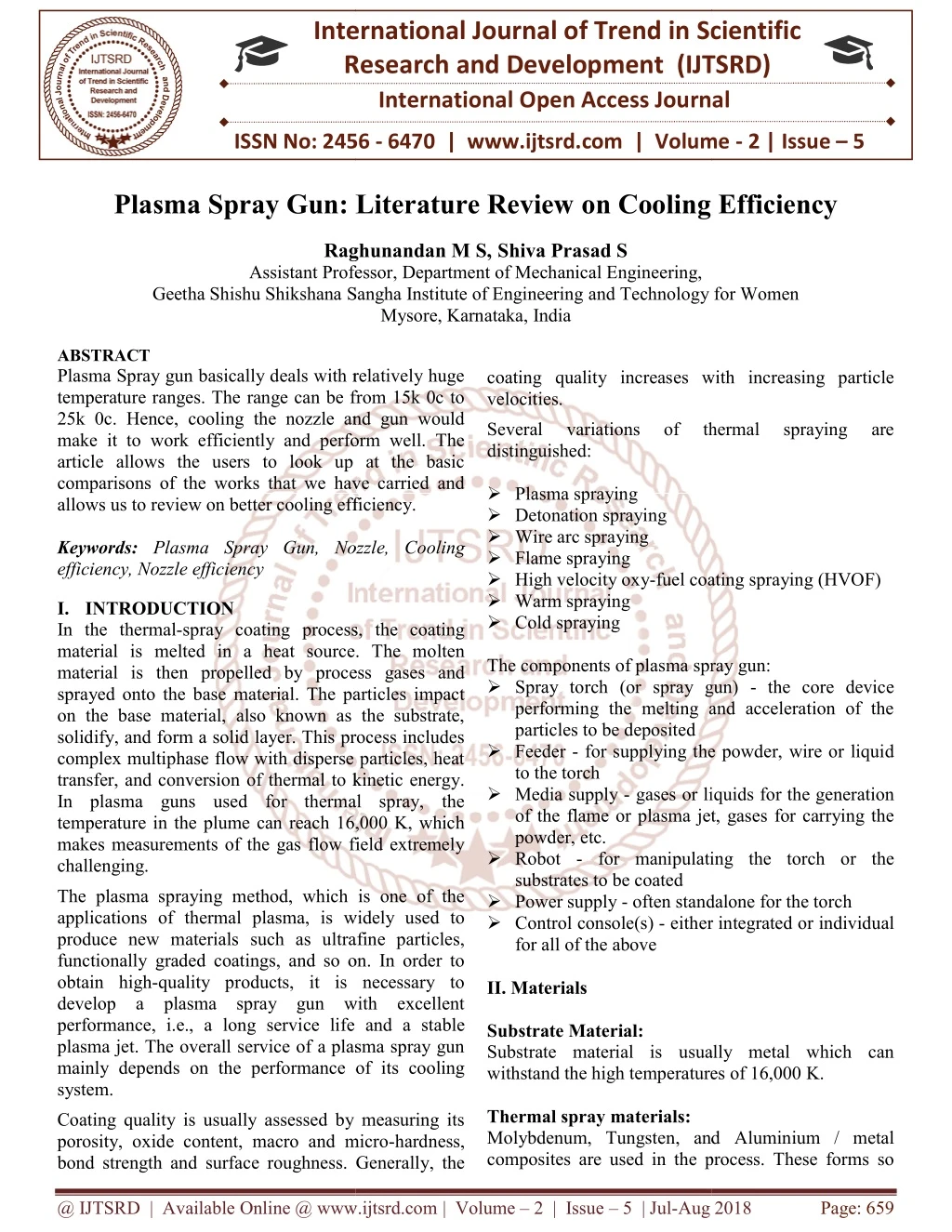
Plasma Spray gun basically deals with relatively huge temperature ranges. The range can be from 15k 0c to 25k 0c. Hence, cooling the nozzle and gun would make it to work efficiently and perform well. The article allows the users to look up at the basic comparisons of the works that we have carried and allows us to review on better cooling efficiency. Raghunandan M S | Shiva Prasad S "Plasma Spray Gun: Literature Review on Cooling Efficiency" Published in International Journal of Trend in Scientific Research and Development (ijtsrd), ISSN: 2456-6470, Volume-2 | Issue-5 , August 2018, URL: https://www.ijtsrd.com/papers/ijtsrd15904.pdf Paper URL: http://www.ijtsrd.com/engineering/mechanical-engineering/15904/plasma-spray-gun-literature-review-on-cooling-efficiency/raghunandan-m-s<br>

E N D
International Research Research and Development (IJTSRD) International Open Access Journal Plasma Spray Gun: Literature Review on Cooling Efficiency International Journal of Trend in Scientific Scientific (IJTSRD) Open Access Journal ISSN No: 2456 ISSN No: 2456 - 6470 | www.ijtsrd.com | Volume 6470 | www.ijtsrd.com | Volume - 2 | Issue – 5 Plasma Spray Gun: Literature Review n Cooling Efficiency Raghunandan M S,Shiva Prasad S Assistant Professor, Department of Mechanical Engineering, Raghunandan M S Assistant Professor Geetha Shishu Shikshana Sangha Institute of Engineering Geetha Shishu Shikshana Sangha Institute of Engineering and Technology for Women Mysore, Karnataka, India and Technology for Women coating quality increases with increasing particle velocities. Several variations of distinguished: Plasma spraying Detonation spraying Wire arc spraying Flame spraying High velocity oxy-fuel coating Warm spraying Cold spraying The components of plasma spray gun: Spray torch (or spray gun) performing the melting and acceleration of the particles to be deposited Feeder - for supplying the powder, wire or liquid to the torch Media supply - gases or liquids for the generation of the flame or plasma jet, gases for carrying the powder, etc. Robot - for manipulating the torch or the substrates to be coated Power supply - often standalone for the torch Control console(s) - either integrated or individual for all of the above II. Materials Substrate Material: Substrate material is usually metal which can withstand the high temperatures of 16,000 K. Thermal spray materials: Molybdenum, Tungsten, and composites are used in the process. These forms so composites are used in the process. These forms so ABSTRACT Plasma Spray gun basically deals with relatively huge temperature ranges. The range can be from 15k 0c to 25k 0c. Hence, cooling the nozzle and gun would make it to work efficiently and perform well. The article allows the users to look up at the basic comparisons of the works that we have carried and allows us to review on better cooling efficiency. Keywords: Plasma Spray Gun, Nozzle, Cooling efficiency, Nozzle efficiency I.INTRODUCTION In the thermal-spray coating process, the coating material is melted in a heat source. The molten material is then propelled by process gases and sprayed onto the base material. The particles impact on the base material, also known as the substrate, solidify, and form a solid layer. This process includes complex multiphase flow with disperse particles, heat transfer, and conversion of thermal to kinetic energy. In plasma guns used for thermal spray, the temperature in the plume can reach 16,000 K, which makes measurements of the gas flow field extremely challenging. The plasma spraying method, which is one of the applications of thermal plasma, is widely used to produce new materials such as ultrafine particles, functionally graded coatings, and so on. In order to obtain high-quality products, it is necessary to develop a plasma spray gun with excellent performance, i.e., a long service life and a stable plasma jet. The overall service of a plasma spray gun mainly depends on the performance of its cooling system. Coating quality is usually assessed by measuring its porosity, oxide content, macro and micro bond strength and surface roughness. Generally, the surface roughness. Generally, the Plasma Spray gun basically deals with relatively huge temperature ranges. The range can be from 15k 0c to 25k 0c. Hence, cooling the nozzle and gun would make it to work efficiently and perform well. The article allows the users to look up at the basic parisons of the works that we have carried and allows us to review on better cooling efficiency. coating quality increases with increasing particle Several variations of thermal thermal spraying spraying are are Plasma Spray Gun, Nozzle, Cooling fuel coating spraying (HVOF) spray coating process, the coating material is melted in a heat source. The molten The components of plasma spray gun: Spray torch (or spray gun) - the core device performing the melting and acceleration of the process gases and sprayed onto the base material. The particles impact on the base material, also known as the substrate, solidify, and form a solid layer. This process includes complex multiphase flow with disperse particles, heat of thermal to kinetic energy. In plasma guns used for thermal spray, the temperature in the plume can reach 16,000 K, which makes measurements of the gas flow field extremely for supplying the powder, wire or liquid gases or liquids for the generation of the flame or plasma jet, gases for carrying the for manipulating the torch or the The plasma spraying method, which is one of the ermal plasma, is widely used to produce new materials such as ultrafine particles, functionally graded coatings, and so on. In order to quality products, it is necessary to develop a plasma spray gun with excellent often standalone for the torch ither integrated or individual vice life and a stable plasma jet. The overall service of a plasma spray gun mainly depends on the performance of its cooling Substrate material is usually metal which can withstand the high temperatures of 16,000 K. Coating quality is usually assessed by measuring its porosity, oxide content, macro and micro-hardness, Molybdenum, Tungsten, and Aluminium / metal @ IJTSRD | Available Online @ www.ijtsrd.com @ IJTSRD | Available Online @ www.ijtsrd.com | Volume – 2 | Issue – 5 | Jul-Aug 2018 Aug 2018 Page: 659
International Journal of Trend in Scientific Research and Development (IJTSRD) ISSN: 2456-6470 called self-bonding coatings. These materials have comparatively high bond metallurgical or diffusion bonding) and can bond to clean polished substrates. Molybdenum and other refractory metals have very high melting points thus the interaction between substrate and coating particles will be increased due to the higher temperatures involved and longer cooling cycles. Also, molybdenum oxide volatilizes and does not get in the way of metallurgical bonding. Aluminum / metal composites produce increased levels of exothermic reaction due to reactions of aluminum with metals like nickel to produce nickel aluminide and with oxygen producing aluminum oxide. The increased thermal action increases degree of diffusion bonding. Higher preheat temperatures for the substrate increase diffusion bonding activities but will also increase oxidation of the substrate which could defeat the objective of higher bond strengths. Plasma spray gases: Gases like Argon, Helium, Hydrogen, Nitrogen mixtures are used in plasma spray process. Coolants: Coolants like nitrogen, carbon dioxide are used to cool the thermal spray process efficiently. These coolants are non-reactive towards the nozzle and other components. Nozzle description: insufficiently cooled are found in the wall near the heat source and in the gasket in the rear of the nozzle. Then, cooling processes with different parameters of cooling water are analyzed. The optimal velocity and direction of cooling water, which efficiently cool the nozzle and improve the service life of the plasma jet, are obtained. strengths (increased Figure 2: Plasma Spray Gun Analyzed Figure 3: Analytical model of the nozzle cooling system. (a) Simplified numerical model of the nozzle. (b) Mesh of the simplified model Figure 2 is a schematic diagram of the analyzed plasma spray gun. This figure shows the nozzle, cooling channel, water outlet, water inlet, etc. The material of the nozzle is red copper. The cooling pump provides cooling water through a loop. The nozzle and the other parts of the gun are cooled by the circulating water through heat exchange. The nozzle is the part most sensitive to changes in cooling efficiency and is easily burned out directly if cooling is insufficient. Governing Equations: 1.The cooling water flow is taken as turbulent fluid flow with a process of heat transfer. According to its characteristics, the processes are assumed in the analysis. Figure 1: Nozzle description Problems/issues in plasma spray gun: Nozzle cooling problem: The nozzle in the plasma spray gun is developed, and the coupled simulation of the flow fluid and heat transfer is carried out with the semi-implicit method for pressure linked equations (SIMPLE) method. Local turbulence, which will lead to appearance of a static-water region, is found at the front corner of the cooling channel in the nozzle. The locations following physical @ IJTSRD | Available Online @ www.ijtsrd.com | Volume – 2 | Issue – 5 | Jul-Aug 2018 Page: 660
International Journal of Trend in Scientific Research and Development (IJTSRD) ISSN: 2456-6470 2.Cooling water is taken as an incompressible liquid and could be simulated by a standard κ−ε turbulence model. Cooling water is constant in flow ability. A two-dimensional model is assumed due to the fact that flow field and heat field are symmetric. The governing equation of the cooling water could be expressed by following equations: The continuity equation node of inlet edge. The relative pressure on every node of outlet edge is 0 mPa. The wall of the cooling channel is taken as a non-penetrating boundary; that is, the velocity parallel to the x-axis is Vx = 0m/s, and the velocity perpendicular to the x-axis is Vy =0m/s on the inner wall. According to the characteristic of the plasma arc, the heat source is simplified as a spot on the inner wall of nozzle. The temperature of the spot is set to 5800 ◦C (This heat spot is assumed to fall on one point of the inner wall instantaneously). The air convection coefficient is 4.32, the air temperature is 27 ◦C, the cooling water convection coefficient is 138.4, and the temperature of the inlet water is 30 ◦C. The temperature of the outside wall is the same as the temperature of the surrounding environment and is set to 27 ◦C. 3. Figure 4: Velocity field of cooling water The SIMPLE method is a basic means to solve problems involving incompressible fluid flow. The basic equations are as follows: The differential equation describing the course of flow and heat transfer: Analysis of flow fields in the corner: As shown in Fig.4, region A and region B are the locations where the static-water phenomenon is most likely to occur. Therefore, region A is chosen in order to analyze the problem of static water. Figure 4a shows an enlargement of region A. The velocity of the flow at the less colored regions (at the corner of the nozzle) is 0 – 0.5m/s. The figure illustrates that these regions are likely static water regions. At the same time, the size of the static water region is illustrated in Fig. 4a, which is in good agreement with theory. Figure 4a shows fluid circumfluence and turbulence. The former is due to convection, and the latter is due to the low-pressure region formed by quick flow. These phenomena agree with basic principles of fluid mechanics. Boundary conditions: The outlet is open to the environment with a constant temperature of 27 ◦C and constant pressure 0 mPa. The fixed velocity Vy =0m/s, Vx is assumed on every @ IJTSRD | Available Online @ www.ijtsrd.com | Volume – 2 | Issue – 5 | Jul-Aug 2018 Page: 661
International Journal of Trend in Scientific Research and Development (IJTSRD) ISSN: 2456-6470 However, the flow separation included in the nozzle was over expanded. So, then the nozzle design was changed to shorten the divergent section of the nozzle. This reduced the Mach umber and thus the over expansion. This modification both further stabilized the plume and reduced energy loss. a b c Figure 7: Re-design of nozzle Figure 5: Magnification of region A. Improvement of Plasma Gun Performance using Comprehensive Fluid Element Modeling The gun is modeled with MHD (magneto- hydrodynamic model). Later the model is subjected to the meshing and boundary conditions, CFD calculation is carried out and is solved. The modeling included the spraying of the particles at the tip of the nozzle since it cannot be mixed directly under the simulation. The first run was made for the Sulzer Metco Triplex ProTM 200. a Simulation result of the chamfer-free structure. b Simulation result of the 45◦ chamfered structure. c Simulation result of the round-corner structure Better Performance of Plasma Thermal Spray Triplex pro 200 plasma gun is formed of three nozzles. The wide nozzle, conventional width nozzle and narrow nozzle. A wide bore, high-enthalpy nozzle produces a slow and hot plasma plume, a medium bore produces a plasma plume typical of most plasma guns, and a narrow bore convergent- divergent supersonic nozzle produces a fast and cool plasma plume. The original 5-mm nozzle was designed to produce supersonic plasma velocities. The formation of shock diamonds in the plasma plume was an indicator that this goal had been achieved. However, the edges of the plume exiting through the divergent section of the nozzle appeared fuzzy—as if the plume was out of focus. Figure 8: Sulzer Metco Triplex Pro TM 200 Preliminary tests revealed the necessity of including the Lorentz force in the model. If not included, three separate arcs stretch from the cathodes to the anodes. Activating this force in the model leads to a unification of the three arcs downstream of the cathodes and the velocity Figure 6: Formation of shock diamonds and flow separation. field gets more @ IJTSRD | Available Online @ www.ijtsrd.com | Volume – 2 | Issue – 5 | Jul-Aug 2018 Page: 662
International Journal of Trend in Scientific Research and Development (IJTSRD) ISSN: 2456-6470 homogeneous at the nozzle exit. In a plasma-spray gun the fluid moving in an external electric field is causing a current density which comprises of three electric arcs and in turn causes an electric field. The interaction of the magnetic field with the current density causes the Lorentz force, which acts on the three arcs. The current is aligned along the main axis, and the magnetic field is oriented clockwise concentrically around the current, therefore the resulting Lorentz force points inwards. This test clearly illustrates the necessity of direct coupling between fluid electromagnetism. If the physics of electromagnetism is only calculated within the post-processing of a gas- only simulation, the same gas flow field would be present whether the Lorentz force is activated or not. For validation purposes, several sets of operating conditions have been run. The geometry has been kept unchanged while the gases, gas flow rates, and electric currents have been changed within a realistic range. Table 1 shows the operating conditions used for the first validation. The properties of the gas mixture Argon-Helium are computed within the code according to the following rules: the density is volume fraction weighted, while conductivity, and specific heat capacity are mass fraction weighted. Mass fraction weighting is used for the calculation of electric conductivity. dynamics and viscosity, thermal Figure 9: The nozzle with-out consideration of Lorentz force and with consideration In the simulation, the operating condition is set by the flow rate and electric current. Gas pressure and potential are then a result of the calculation and can be compared to the test data. First validation results are listed in Table 2. Figure 10: Velocity distribution of gas flow for plasma arc without (a) and with (b) Lorentz force (red = high, blue = low velocity magnitude) With the exception of case 1 all other predictions of voltage by MHD are within 10% of the average values measured during testing. These results are quite remarkable as they have been obtained by a simulation setup which has been run as a complete set for the first time without any parameter tuning based on experiments. The fact that voltage prediction is in general too high suggests some systematic offset that could be verified and, if necessary, corrected by Figure 11: Visualization of current density (red= high, green = low) In-between the three cathodes and the anode ring with Lorentz force @ IJTSRD | Available Online @ www.ijtsrd.com | Volume – 2 | Issue – 5 | Jul-Aug 2018 Page: 663
International Journal of Trend in Scientific Research and Development (IJTSRD) ISSN: 2456-6470 further validations. Observations of wear traces in a spray gun which has been operated for some time can be used for qualitative validations. For example, the emission points of the arcs on the electrodes leave marks on the surface due to the extreme temperatures. This can be directly compared to MHD results by plotting an iso-surface of temperature to visualize the arcs as shown in Fig. 9. The comparison illustrates that the location of the arc emission can be quite well captured by the simulation. References 1.Better Performance of Plasma Thermal Spray by RONALD J. MOLZ, MCCULLOUGH, SULZER METCO, TORSTEN WINTERGERSTE, SULZER INNOTEC RICHARD J. 2.Improvement of Plasma Gun Performance using Comprehensive Fluid Element Modeling: Part I Felix A. Muggli, Ronald J. Molz, Richard McCullough, and Dave Hawley 3.Numerical simulation of fluid flow and heat transfer in a plasma spray gun by WeimingWang, Dayong Li, Jie Hu, Yinghong Peng, Yishun Zhang, Deyuan Li Figure 12: Left, predicted emission points at cathodes (insulator removed for clarity) and right, TriplexProTM-200 cathodes and insulator after testing. @ IJTSRD | Available Online @ www.ijtsrd.com | Volume – 2 | Issue – 5 | Jul-Aug 2018 Page: 664