Download
1 / 6
80 likes | 175 Views
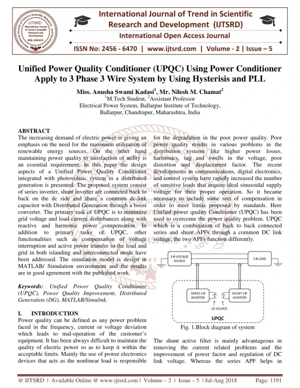
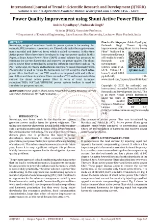
In a powers system network there are many problems related to power quality. So to improve power quality of a system we use different devices such as active power filters. Active power filters are classified into two types that is Shunt Active Power Filter APF and Series Active Power Filter APF and combination of both is known as UPQC Unified Power Quality Conditioner . Here we have done simulation of Shunt Active Power Filter, Series Active Power Filter and Unified Power Quality Conditioner. Shunt APF is used to mitigate the problems due to current harmonics which is because of non linear load and make source current sinusoidal and distortion free. The control scheme used is hysteresis current controller using "p q theory. Series APF is used to mitigate problems caused due to voltage distortion and unbalance present in source voltage and make load voltage perfectly balanced and regulated. The control scheme used is Hysteresis voltage controller by using a b c to d q transformations. Then Shunt APF and Series APF is combined for designing UPQC and by this current harmonics in load current and voltage unbalances in source voltage both are removed and source current becomes sinusoidal and load voltage becomes perfectly balanced. Kishankumar V. Dave | Sandip B. Parmar "Power Quality Improvement by Unified Power Quality Conditioner" Published in International Journal of Trend in Scientific Research and Development (ijtsrd), ISSN: 2456-6470, Volume-3 | Issue-1 , December 2018, URL: https://www.ijtsrd.com/papers/ijtsrd19088.pdf Paper URL: http://www.ijtsrd.com/engineering/electrical-engineering/19088/power-quality-improvement-by-unified-power-quality-conditioner/kishankumar-v-dave<br>

E N D
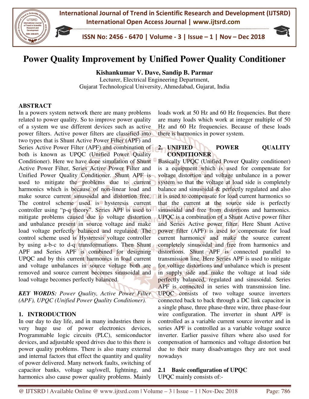
International Journal of Trend in International Open Access International Open Access Journal | www.ijtsrd.com International Journal of Trend in Scientific Research and Development (IJTSRD) Research and Development (IJTSRD) www.ijtsrd.com ISSN No: 2456 ISSN No: 2456 - 6470 | Volume - 3 | Issue – 1 | Nov 1 | Nov – Dec 2018 Power Quality Improvement b Improvement by Unified Power Quality Conditioner y Unified Power Quality Conditioner Kishankumar V. Lecturer Gujarat Technological University Gujarat Technological University,Ahmedabad, Gujarat, India Kishankumar V. Dave, Sandip B. Parmar Lecturer, Electrical Engineering Department, ABSTRACT In a powers system network there are many problems related to power quality. So to improve power quality of a system we use different devices such as active power filters. Active power filters are classified into two types that is Shunt Active Power Filter (APF) and Series Active Power Filter (APF) and combination of both is known as UPQC (Unified Power Quality Conditioner). Here we have done simulation of Shunt Active Power Filter, Series Active Power Filter and Unified Power Quality Conditioner. Shunt APF is used to mitigate the problems due to current harmonics which is because of non-linear load and make source current sinusoidal and distortion free. The control scheme used is hysteresis current controller using “p-q theory”. Series APF is used mitigate problems caused due to voltage distortion and unbalance present in source voltage and make load voltage perfectly balanced and regulated. The control scheme used is Hysteresis voltage controller by using a-b-c to d-q transformations. Then Shunt APF and Series APF is combined for designing UPQC and by this current harmonics in load current and voltage unbalances in source voltage both are removed and source current becomes sinusoidal and load voltage becomes perfectly balanced. KEY WORDS: Power Quality, Active Power Filter (APF), UPQC (Unified Power Quality Conditioner) 1.INTRODUCTION In our day to day life, and in many industries there is very huge use of power electronics devices, Programmable logic circuits (PLC), semiconductor devices, and adjustable speed drives due to this there is power quality problems. There is also many extern and internal factors that effect the quantity and quality of power delivered. Many network faults, switching of capacitor banks, voltage sag/swell, lightning, and harmonics also cause power quality problems. Mainly harmonics also cause power quality problems. Mainly loads work at 50 Hz and 60 Hz freque are many loads which work at integer multiple of 50 Hz and 60 Hz frequencies. Because of these loads there is harmonics in power system 2.UNIFIED POWER CONDITIONER Basically UPQC (Unified Power Quality conditioner) is a equipment which is used for compensate for voltage distortion and voltage unbalance in a power system so that the voltage at load side is completely balance and sinusoidal & perfectly regulated and also it is used to compensate for load current harmonics so that the current at the source side is perfectly sinusoidal and free from distortions and harmonics. UPQC is a combination of a Shunt Active power filter and Series Active power filter. Here Shunt Active power filter (APF) is used to compensate for load current harmonics and make the source current completely sinusoidal and free from harmonics and distortions. Shunt APF is connected parallel to transmission line. Here Series APF is used to mitigate for voltage distortions and unbalance which is present in supply side and make the voltage at load side perfectly balanced, regulated and sinusoidal. Series APF is connected in series with transmission line. UPQC consists of two voltage source inverters connected back to back through a DC link capacitor in a single phase, three phase-three wire, three phase wire configuration. The inverter in shunt APF is controlled as a variable current source inverter and in series APF is controlled as a variable voltage source inverter. Earlier passive filters where also used for compensation of harmonics and voltage distortion but due to their many disadvantages they are not used nowadays 2.1 Basic configuration of UPQC UPQC mainly consists of:- In a powers system network there are many problems related to power quality. So to improve power quality of a system we use different devices such as active power filters. Active power filters are classified into loads work at 50 Hz and 60 Hz frequencies. But there are many loads which work at integer multiple of 50 Hz and 60 Hz frequencies. Because of these loads there is harmonics in power system. er Filter (APF) and UNIFIED POWER QUALITY QUALITY Series Active Power Filter (APF) and combination of both is known as UPQC (Unified Power Quality Conditioner). Here we have done simulation of Shunt Active Power Filter, Series Active Power Filter and Basically UPQC (Unified Power Quality conditioner) which is used for compensate for voltage distortion and voltage unbalance in a power system so that the voltage at load side is completely balance and sinusoidal & perfectly regulated and also it is used to compensate for load current harmonics so current at the source side is perfectly sinusoidal and free from distortions and harmonics. UPQC is a combination of a Shunt Active power filter and Series Active power filter. Here Shunt Active power filter (APF) is used to compensate for load rmonics and make the source current completely sinusoidal and free from harmonics and distortions. Shunt APF is connected parallel to transmission line. Here Series APF is used to mitigate for voltage distortions and unbalance which is present de and make the voltage at load side perfectly balanced, regulated and sinusoidal. Series APF is connected in series with transmission line. UPQC consists of two voltage source inverters connected back to back through a DC link capacitor in three wire, three phase-four wire configuration. The inverter in shunt APF is controlled as a variable current source inverter and in series APF is controlled as a variable voltage source inverter. Earlier passive filters where also used for ompensation of harmonics and voltage distortion but due to their many disadvantages they are not used Shunt APF is used to mitigate the problems due to current linear load and make source current sinusoidal and distortion free. The control scheme used is hysteresis current q theory”. Series APF is used to mitigate problems caused due to voltage distortion and unbalance present in source voltage and make load voltage perfectly balanced and regulated. The control scheme used is Hysteresis voltage controller q transformations. Then Shunt APF and Series APF is combined for designing UPQC and by this current harmonics in load current and voltage unbalances in source voltage both are removed and source current becomes sinusoidal and load voltage becomes perfectly balanced. Quality, Active Power Filter (APF), UPQC (Unified Power Quality Conditioner). In our day to day life, and in many industries there is very huge use of power electronics devices, Programmable logic circuits (PLC), semiconductor devices, and adjustable speed drives due to this there is power quality problems. There is also many external and internal factors that effect the quantity and quality of power delivered. Many network faults, switching of capacitor banks, voltage sag/swell, lightning, and Basic configuration of UPQC @ IJTSRD | Available Online @ www.ijtsrd.com www.ijtsrd.com | Volume – 3 | Issue – 1 | Nov-Dec 2018 Dec 2018 Page: 786
International Journal of Trend in Scientific Research and Development (IJTSRD) ISSN: 2456 International Journal of Trend in Scientific Research and Development (IJTSRD) ISSN: 2456 International Journal of Trend in Scientific Research and Development (IJTSRD) ISSN: 2456-6470 Series APF:- In a transmission line series APF is connected in series. It is connected to the transmission line with the transformer. Series APF is a voltage source inverter connected in series with transmission line. It is used to compensate or mitigate the problems which comes due to voltage distortions and voltage unbalances. The series APF injects a compensating voltage so that load voltage will be perfectly balanced and regulated. Controlling of series inverter is done by PWM (pulse width modulation) techniques. Here we used Hysteresis band PWM techniques as it implementation is easy. Also its response is fast. Its details are explained in subsequent sections. Shunt APF: - In a transmission line shunt APF is generally connected in parallel. Shunt APF is used to compensate for distortions & harmonics which are produced due to current. Due to non- linear load there is harmonics in load current, so to keep source current completely sinusoidal and distortion free we uses Shunt APF. Shunt APF injects compensating current so that the source current is completely sinusoidal and free from distortions. Controlling of Shunt APF is done by hysteresis band PWM techniques. In hysteresis band PWM techniques output current follows the reference and current and is within the fixed hysteresis band. Series Transformer:- The necessary voltage which is generated by series APF so that the voltage at load side is perfectly balanced and regulated i.e. Sinusoidal is injected into the transmission line with the help of these transformers. The series transformer turns ratio should be suitable so that injected voltage is suitable such that it injects a compensating voltage which will completely make the load side voltage balanced and also it reduces the current flowing through series inverter. Low Pass Filter:- Low pass filter is used at the output of series inverter so that the high frequency voltage components are removed which is produced due to switching of Voltage source inverter. High pass filter:- High pass filter is used at output of shunt inverter so that the ripples which are produced due to currents switching are absorbed. DC link capacitor:- The two voltage source inverter are connected back to back through a DC capacitor. DC capacitor is provides a DC voltage for working of both the inverter. The DC capacitor also provides a both the inverter. The DC capacitor also provides a In a transmission line series APF is real power difference between source and load during eriod and also acts as a energy storage elements. During steady state real power supplied by source should be equal to the sum real power demand of load & a small amount of power which compensates for active filter. DC capacitor voltage reference value but due to disturbance in real power balance between source and load due to change in load conditions the DC capacitor value is changed from reference value. real power difference between source and load during the transient period and also acts as a energy storage elements. During steady state real power supplied by source should be equal to the sum real power demand of load & a small amount of power which compensates for active filter. DC capacitor voltage should be equal to reference value but due to disturbance in real power balance between source and load due to change in load conditions the DC capacitor value is changed from reference value. to the transmission line with the transformer. Series APF is a voltage source inverter connected in series with transmission line. It is used to compensate or mitigate the problems which comes due to voltage distortions and voltage APF injects a compensating voltage so that load voltage will be perfectly balanced and regulated. Controlling of series inverter is done by PWM (pulse width modulation) techniques. Here we used Hysteresis band PWM techniques as it lso its response is fast. Its details are explained in subsequent sections. In a transmission line shunt APF is generally connected in parallel. Shunt APF is used to compensate for distortions & harmonics which are linear load there is harmonics in load current, so to keep source current completely sinusoidal and distortion free we uses Shunt APF. Shunt APF injects compensating current so that the source current is completely sinusoidal and tions. Controlling of Shunt APF is done by hysteresis band PWM techniques. In hysteresis band PWM techniques output current follows the reference and current and is within the Fig1. Configuration of UPQC Fig1. Configuration of UPQC 3.POWER FLOW ANALYSIS OF UPQC IN STEADY STATE UPQC is used to eliminate harmonics present in current and distortions of voltage and is used for reactive power compensation. In UPQC series APF is used as voltage source inverter to compensate for voltage distortions and make voltage at load side completely balanced and sinusoidal. Series APF injects a voltage which is difference of source and perfectly balanced load voltage. Shunt APF is used as to eliminate harmonics present in load current so that source current is completely sinusoidal and also used for compensation of reactive power. Shunt APF is also used to maintain value of DC link capacitor constant. POWER FLOW ANALYSIS OF UPQC IN s used to eliminate harmonics present in current and distortions of voltage and is used for reactive power compensation. In UPQC series APF is used as voltage source inverter to compensate for voltage distortions and make voltage at load side lanced and sinusoidal. Series APF injects a voltage which is difference of source voltage and perfectly balanced load voltage. Shunt APF is used as to eliminate harmonics present in load current so that source current is completely sinusoidal and also for compensation of reactive power. Shunt APF is also used to maintain value of DC link capacitor The necessary voltage which is rated by series APF so that the voltage at load side is perfectly balanced and regulated i.e. Sinusoidal is injected into the transmission line with the help of these transformers. The series transformer turns ratio age is suitable such that it injects a compensating voltage which will completely make the load side voltage balanced and also it reduces the current flowing through series Low pass filter is used at the output of series inverter so that the high frequency voltage components are removed which is produced due to High pass filter is used at output of hat the ripples which are produced The two voltage source inverter are connected back to back through a DC capacitor. DC capacitor is provides a DC voltage for working of Fig2. Circuit diagram of UPQC Fig2. Circuit diagram of UPQC @ IJTSRD | Available Online @ www.ijtsrd.com www.ijtsrd.com | Volume – 3 | Issue – 1 | Nov-Dec 2018 Dec 2018 Page: 787
International Journal of Trend in Scientific Research and Development (IJTSRD) ISSN: 2456 International Journal of Trend in Scientific Research and Development (IJTSRD) ISSN: 2456 International Journal of Trend in Scientific Research and Development (IJTSRD) ISSN: 2456-6470 3.1 Shunt Active Power Filter Active power filters are devices which generates the same amount of harmonics which are generated by load but at 1800 phase shifted. Active power filters are devices such as amplifiers etc. Shunt APF injects the compensating current in the line at the point of common coupling (PCC) so that the current at source sides become completely sinusoidal and free from distortions. due to presence of non-linear load there is harmonics & distortions in load current due to which source current also get effected and source current becomes non-sinusoidal and distorted. So to remove this non-sinusoidal behavior of source current we use Shunt APF which provides the compensating current which is same as harmonic generated by load but 1800 phase shifted and this compensating current is given at PCC which helps in removing distortions from source current and makes source current completely sinusoidal. Shunt APF is also used for reactive power compensation & it also removes all problems which arises due to current harmonics. The control scheme used in Shunt APF is instantaneous reactive power theory also known as “p-q theory”. p-q theory is used to generate the reference current and this reference current is given to Hysteresis current controller along with compensating current (actual output current) of Shunt APF. Hysteresis current controller is used to generate gating signal which is then given to voltage source inverter. 3.2Steps for controlling shunt APF 1.Generation of reference compensating current 2.Generation of gating signal by hysteresis current controller 3.3 Block diagram of shunt APF domain transformations, here abc phases are transformed into αβ0 coordinates. The coordinate 0 corresponds to a zero sequence component. “p theory” corresponds to a algebraic transf which is known as Advantages of “p-q theory” it is simple as it only requires algebraic operations. It is applicable for steady state and transient state operation. In this theory abc phases are converted to 0 are. Here voltages and load currents are taken and it is converted from. After that power calculation is real power and imaginary power is calculated. After that power which is to be compensated is found out. The power loss across DC capacitor should also be found with the help of PI controller. Gain of PI controller is kept proper. Power which is to be compensated are harmonic component of real power and whole imaginary power. Then after this current is calculated in − coordinates. This cur coordinates are transformed into Clarke’s transformation. This is the reference compensating current. It is given to hysteresis current controller along with shunt APF actual output current. In current calculation low pass fi higher order harmonics of power. 4.Series Active Power Filter A series active power filter is equipment which is used to mitigate the problems which are caused due to voltage distortions and voltage unbalance in source voltage. The voltage distortions and unbalance means voltage dip, voltage rise, voltage fluctuations, voltage flicker these are removed from the source voltage by means of Series APF. A series APF injects a voltage component in series with supply voltage and removes harmonic component and distortions, unbalance present in voltage waveform. The series APF is used to remove all these voltage problems from supply voltage and make load voltage perfectly balanced and regulated. Series APF is connected in series with transmission line with a series transformer. The turns ratio of series transformer should be proper so that the injected voltage should come properly. Here three phase reference voltage is calculated by transforming − − to − − 0 reference frame and again by transforming −− 0 to − − frame. After that the reference voltage is given to hysteresis voltage controller with the actual output voltage of series APF (voltage we got across series transformer) and the PWM signal is generated which is given to voltage source inverter. The DC voltage is given across VSI so to get real power difference between source and load. to get real power difference between source and load. domain transformations, here abc phases are 0 coordinates. The coordinate 0 corresponds to a zero sequence component. “p-q theory” corresponds to a algebraic transformations which is known as q theory” it is simple as it only requires algebraic operations. It is applicable for steady state and transient state operation. In this theory abc phases are converted to 0 are. Here source voltages and load currents are taken and it is converted After that power calculation is real power and imaginary power is calculated. After that power which is to be compensated is found out. The power loss across DC capacitor should also be found. out. It is found with the help of PI controller. Gain of PI controller is kept proper. Power which is to be compensated are harmonic component of real power and whole imaginary power. Then after this current is − coordinates. This currents in − coordinates are transformed into − − axis by inverse Clarke’s transformation. This is the reference compensating current. It is given to hysteresis current controller along with shunt APF actual output current. In current calculation low pass filter is used to remove higher order harmonics of power. Active power filters are devices which generates the are generated by load but at 1800 phase shifted. Active power filters are devices such as amplifiers etc. Shunt APF injects the compensating current in the line at the point of common coupling (PCC) so that the current at source Clarke’s Clarke’s transformation. transformation. usoidal and free from linear load there is harmonics & distortions in load current due to which source current also get effected and source current sinusoidal and distorted. So to remove ehavior of source current we use Shunt APF which provides the compensating current which is same as harmonic generated by load but 1800 phase shifted and this compensating current is given at PCC which helps in removing distortions from source makes source current completely sinusoidal. Shunt APF is also used for reactive power compensation & it also removes all problems which arises due to current harmonics. The control scheme used in Shunt APF is instantaneous reactive power q theory is used to generate the reference current and this reference current is given to Hysteresis current controller along with compensating current (actual output current) of Shunt APF. Hysteresis current controller is used to te gating signal which is then given to voltage Series Active Power Filter A series active power filter is equipment which is used to mitigate the problems which are caused due to voltage distortions and voltage unbalance in source ltage distortions and unbalance means voltage dip, voltage rise, voltage fluctuations, voltage flicker these are removed from the source voltage by means of Series APF. A series APF injects a voltage component in series with supply voltage and removes onic component and distortions, unbalance present in voltage waveform. The series APF is used to remove all these voltage problems from supply voltage and make load voltage perfectly balanced and regulated. Series APF is connected in series with on line with a series transformer. The turns ratio of series transformer should be proper so that the injected voltage should come properly. Here three phase reference voltage is calculated by transforming − − 0 reference frame and again by −− 0 to − − frame. After that the reference voltage is given to hysteresis voltage controller with the actual output voltage of series APF (voltage we got across series transformer) and the PWM signal is generated which is given to voltage rter. The DC voltage is given across VSI so Generation of reference compensating current Generation of gating signal by hysteresis current Fig3. Basic control design of shunt APF control design of shunt APF 3.4 Control scheme of shunt APF Control pattern used in shunt APF is instantaneous reactive power theory which is also known as “p theory”. It was introduced by Akagi et al in 1983. The instantaneous reactive power theory is based on time instantaneous reactive power theory is based on time Control pattern used in shunt APF is instantaneous reactive power theory which is also known as “p-q et al in 1983. The @ IJTSRD | Available Online @ www.ijtsrd.com www.ijtsrd.com | Volume – 3 | Issue – 1 | Nov-Dec 2018 Dec 2018 Page: 788
International Journal of Trend in Scientific Research and Development (IJTSRD) ISSN: 2456 International Journal of Trend in Scientific Research and Development (IJTSRD) ISSN: 2456 International Journal of Trend in Scientific Research and Development (IJTSRD) ISSN: 2456-6470 4.1 Block Diagram of Series APF Supply Voltage Line impedance Rs= 0.01 DC Voltage DC capacitor Load impedance RL=0.0001, Line frequency Table-1 System Parameters used for Shunt APF 1 System Parameters used for Shunt APF 400 V 400 V Rs= 0.01, Ls= 1 H 850 V 500 F RL=0.0001, LL=1 H 50 Hz 850 V 500 F 50 Hz Fig.4. Basic Control design of Series APF Fig.4. Basic Control design of Series APF 4.2Steps for controlling series APF 1.Generation of reference compensating voltage 2.Comparing reference compensating voltage with actual compensating voltage in hysteresis voltage controller and generating PWM signal for voltage source inverter 4.3 Control scheme of series APF The control pattern of series APF is based on Park’s transformation or 0 transformation. Here we compared the reference voltage with actual output voltage of series APF. The supply voltage is first converted into 0 coordinates form phases. Then this output voltage is compared with input reference voltage which is first converted into coordinates. After comparing this two voltages they are again transformed from coordinates to phases. The required in converting to coordinates or vice versa we get from PLL (phase locked loop). After this the supply voltage is given to PLL and is generated. Then this along with output voltages are transformed into phases which is the reference output voltage. Then this reference output voltage (vc*) is compared with sensed series APF output voltage (vc) in hysteresis voltage controller and PWM signal is generated which is given to VSI. The PLL is a control system that generates an output signal whose phase is related to phase of an input signal. For simplicity zero sequence component is ignored. 5.RESULTS AND DISCUSSIONS The simulation results are discussed in this chapter. In Shunt APF “p-q theory” and hysteresis current controller was used for getting simulation results. In Series APF “dq0 transformation” and hysteresis voltage controller were used for getting simulation results. After that Shunt APF and Series APF were combined to get simulation results and Combination is known as UPQC. Generation of reference compensating voltage Comparing reference compensating voltage with actual compensating voltage in hysteresis voltage controller and generating PWM signal for voltage Fig.5 Load current of Shunt APF Fig.5 Load current of Shunt APF In fig.5 the waveform of load current of shunt APF is given and they are not sinusoidal due to presence of non-linear loads. This is non are Non-linear due to presence non diode etc the waveform of load current of shunt APF is given and they are not sinusoidal due to presence of linear loads. This is non-linear waveform. They linear due to presence non-linear loads like The control pattern of series APF is based on Park’s transformation or 0 transformation. Here we compared the reference voltage with actual output voltage of series APF. The supply voltage is first converted into 0 coordinates form phases. Then this output voltage is compared with input reference which is first converted into coordinates. After comparing this two voltages they are again transformed from coordinates to phases. The required in converting to coordinates or vice versa we get from PLL (phase locked loop). After this the supply voltage is given to PLL and is generated. Then this along with output voltages are transformed into phases which is the reference output voltage. Then this reference output voltage (vc*) is compared with sensed series APF output voltage (vc) in hysteresis voltage controller and PWM signal is generated which is given to VSI. The PLL is a control system that generates an output signal whose phase is related to phase of an input signal. For simplicity zero sequence component Fig.6 Source current of Shunt APF Fig.6 Source current of Shunt APF Fig. 6 shows source current of shunt APF. The source current contains harmonics till 0.01 sec as up to this time shunt APF is not in operation. After 0.01 sec shunt APF starts operating in a system. So after 0.01 sec the harmonics are removed from source curren The time of operation of shunt APF is controlled by circuit breaker. 6 shows source current of shunt APF. The source current contains harmonics till 0.01 sec as up to this time shunt APF is not in operation. After 0.01 sec shunt APF starts operating in a system. So after 0.01 sec the harmonics are removed from source current. The time of operation of shunt APF is controlled by mulation results are discussed in this chapter. In q theory” and hysteresis current controller was used for getting simulation results. In Series APF “dq0 transformation” and hysteresis voltage controller were used for getting simulation ts. After that Shunt APF and Series APF were combined to get simulation results and Combination is Fig.7 Injected current by Shunt APF Fig.7 Injected current by Shunt APF In fig.7 the current injected by shunt APF is given the current is injected from 0.01 sec. As shunt APF starts operation from 0.01 sec. After 0 current will become completely sinusoidal. In fig.7 the current injected by shunt APF is given the current is injected from 0.01 sec. As shunt APF starts operation from 0.01 sec. After 0.01 sec the source current will become completely sinusoidal. @ IJTSRD | Available Online @ www.ijtsrd.com www.ijtsrd.com | Volume – 3 | Issue – 1 | Nov-Dec 2018 Dec 2018 Page: 789
International Journal of Trend in Scientific Research and Development (IJTSRD) ISSN: 2456 International Journal of Trend in Scientific Research and Development (IJTSRD) ISSN: 2456 International Journal of Trend in Scientific Research and Development (IJTSRD) ISSN: 2456-6470 UPQC model was developed by joining Shunt APF and series APF back to back using DC capacitor. The controlling techniques used here are hysteresis band controller. The simulation is done and current harmonics are removed and source current is completely sinusoidal. And the voltage dip/rise in supply side is mitigated and load voltage is perfectly balanced. The THD of source current is within the limit that is less than 6%. The UPQC model can be enhanced and enriched to terminate the power quality system. The various ways for doing that: prototype of this UPQC model can be esatablished in laboratory. UPQC model can be established for three phase four wire system for the non unstable voltage. Here the UPQC mode was right shunt UPQC, further we can develop model for left shunt UPQC REFERENCES 1.H. Akagi, “Trends in active line conditioner”, IEEE Transactions on Power Electronics no.3, 1994. 2.H. Fujita and H. Akagi, Quality Conditioner: The integration of series and shunt active filters” IEEE Transactions on Power Electronics, vol.13, no.2 March 1998. 3.N. Hingorani, “Introducing Custom Power,” Spectrum, Vol.32, Issue: 6, June 1995,pp 41 4.H. Awad, M. H. J Bollen, “Power Power Quality Improvements,” on Industrial Electronics, 2003, vol.2, pp. 1129 1136 5.Bhim Singh, Kamal Al Chandra , “A Review of Active Filters for Power Quality Improvement” IEEE Trans. on Industrial Electronics, Vol.46, No.5, oct. 1999, pp.960 6.H. Akagi, Y. Kanazawa, A. Nabae , “Generalized Theory of the Instantaneous Reactive Power in Three Phase Circuits”, in Tokyo’83 InternationalConf. Power Tokyo,.pp.1375-1386. 7.H. Akagi, Y. Kanazawa, and A. Nabae, “Instantaneous reactive power compensators comprising switching devices without energy storage components,” IEEE Transactions Applications, vol. IA-20, pp. 625 1984. 5.1 Voltages across series APF during sag As given in Fig.8 it is the source voltage during sag. Sag time interval is 0.08 sec to 0.3 sec. The sag is due to voltage unbalance that may be caused due to faults to voltage unbalance that may be caused due to faults. Voltages across series APF during sag it is the source voltage during sag. Sag time interval is 0.08 sec to 0.3 sec. The sag is due was developed by joining Shunt APF and series APF back to back using DC capacitor. The controlling techniques used here are hysteresis band controller. The simulation is done and current harmonics are removed and source current is letely sinusoidal. And the voltage dip/rise in supply side is mitigated and load voltage is perfectly balanced. The THD of source current is within the The UPQC model can be enhanced and enriched to terminate the power quality problems in a power system. The various ways for doing that:-The prototype of this UPQC model can be esatablished in UPQC model can be established for three phase four wire system for the non-linear load and Here the UPQC model developed was right shunt UPQC, further we can develop model Fig.8 Source voltage of series APF during sag Fig.8 Source voltage of series APF during sag The Fig.9 shows the load voltage of series APF that is completely sinusoidal and perfectly balanced. As after application of series APF the load voltage becomes balanced. The sag at time interval 0.08 sec to 0.3 sec are removed by the help of series APF. The load voltage becomes free from all unbalance which was caused due voltage dip. The Fig.9 shows the load voltage of series APF that is mpletely sinusoidal and perfectly balanced. As after application of series APF the load voltage becomes balanced. The sag at time interval 0.08 sec to 0.3 sec are removed by the help of series APF. The load voltage becomes free from all unbalance which was H. Akagi, “Trends in active line conditioner”, Power Electronics, vol.9, H. Fujita and H. Akagi, “The Unified Power The integration of series and IEEE Transactions on Power , vol.13, no.2 March 1998. Fig 9 Load voltage of series APF during sag Fig 9 Load voltage of series APF during sag 6.CONCLUSIONS AND FUTURE SCOPE Unified quality conditioner was studied and investigated in this thesis for power quality enrichment. UPQC is a type of advance hybrid filter which uses series APF for removal of voltage related problems like voltage dip/rise, fluctuation, imbalance and shunt APF for removal of harmonics in current harmonics. What type of problems are there in power quality was studied and discussed. UPQC system is developed and discussed in detail. The simulink models of Shunt APF , Series APF, UPQC are developed. Shunt APF model is developed using “p and control techniques used here is hysteresis current controller. The simulation is done and current harmonics are eliminated and current drawn from source is completely sinusoidal. The THD of source current is within the limit that is 5.2%. Series APF model is developed using Park’s transformation and controlling techniques used are hysteresis voltage controller. The simulation is done and source voltage dip/rise are mitigated and load voltage is made completely balanced. CONCLUSIONS AND FUTURE SCOPE Unified quality conditioner was studied and investigated in this thesis for power quality enrichment. UPQC is a type of advance hybrid filter which uses series APF for removal of voltage related problems like voltage dip/rise, fluctuation, imbalance unt APF for removal of harmonics in current harmonics. What type of problems are there in power quality was studied and discussed. UPQC system is developed and discussed in detail. The simulink models of Shunt APF , Series APF, UPQC are N. Hingorani, “Introducing Custom Power,” IEEE , Vol.32, Issue: 6, June 1995,pp 41-48. J Bollen, “Power Electronics for Power Quality Improvements,” IEEESymposium , 2003, vol.2, pp. 1129- Bhim Singh, Kamal Al-Haddad and Ambrish Chandra , “A Review of Active Filters for Power IEEE Trans. on Industrial , Vol.46, No.5, oct. 1999, pp.960-971.. H. Akagi, Y. Kanazawa, A. Nabae , “Generalized Theory of the Instantaneous Reactive Power in Three Phase Circuits”, in Proeedings. IPEC- Conf. PowerElectronics, model is developed using “p-q Theory” and control techniques used here is hysteresis current controller. The simulation is done and current harmonics are eliminated and current drawn from source is completely sinusoidal. The THD of source H. Akagi, Y. Kanazawa, and A. Nabae, “Instantaneous reactive power compensators comprising switching devices without energy IEEE TransactionsIndustry 20, pp. 625-30, May/June model is developed using Park’s transformation and controlling techniques used are hysteresis voltage controller. The simulation is done and source voltage dip/rise are mitigated and load @ IJTSRD | Available Online @ www.ijtsrd.com www.ijtsrd.com | Volume – 3 | Issue – 1 | Nov-Dec 2018 Dec 2018 Page: 790
International Journal of Trend in Scientific Research and Development (IJTSRD) ISSN: 2456 International Journal of Trend in Scientific Research and Development (IJTSRD) ISSN: 2456 International Journal of Trend in Scientific Research and Development (IJTSRD) ISSN: 2456-6470 8.E. H. Watanabe, R. M. Stephen, and M. Arcdes, “New concept of instantaneous active andreactive powers in electric systems with generic load,” IEEE Transactions. on Power Delivery April 1993, pp 697-703. 9.Rosli Omar, Nasrudin Abd Rahim, Marizan sulaiman “Modeling and Simulation f sags/swells mitigation using dynamic voltage restorer (DVR)” IEEE journal on Power Electronics Drives and Energy System. 10.M. A. Chaudhari and Chandraprakash, “Three Phase Series Active Power Filter as Power Quality Conditioner,” IEEE International Conference on Power Electronics, Drives andEnergy Systems Dec. 2012, pp 1-6. 11.A. Banerji, S. K. Biswas, B. Singh, “DSTATCOM Control Algorithms: A Review,”International Journal of Powr Electronics and Drive System (IJPEDS), Vol.2, No.3,September 2012, p 296. 12.Mehmet Ucar and Engin Ozdemir, “Control of a 3-phase 4-leg active power filter under non mains voltage condition,” Electric Power Systems Research 78 (2008) 58–73. 13.Srinivas Bhaskar Karanki, Mahesh K. Mishra,B. Kalyan Kumar,"Particle Swarm Optimization Based Feedback Controller for Unified Power Quality Conditioner", "IEEETransactions on Power Delivery, vol. 25, no. 4, October 2010". 14.Vasudhra Mahajan, Pramod Agarwal, Hri Om Gupta “Simulation of shunt active powerfilter using Instantaneous conference on Applied Power Electronics. 15.Matin Kesler, Angin Ozadmir, “Synchronous Reference Frame based Control method of UPQC under balanced and distorted load conditions”, IEEE Transactions on Industrial vol.58, no.9, Sep 2011. 16.Bhim Singh, Kamal Al Chandra , “A Review of Active Filters for Power Quality Improvement” IEEE Transactions on Industrial Electronics, Vol.46, No.5, oct 1999, pp 960-971. 17.Fang Zheng Peng,and Jih Instantaneous Reactive Power Theory for Three phase Power Systems”IEEE Transactions on Instrumentation and Measurement February 1996. 18.Yash Pal, A. Swarup, Bhim Singh, “A control strategy based on UTT and Ic of three wire UPQC for power International Journal of Engineering, Technology Vol. 3, No. 1, 2011, pp. 30 19.Metin Kesler and Engin Ozdemir, “A Novel Control Method for Unified Power Quality Conditioner (UPQC) Under Non Voltage and Unbalanced Load Conditions,” Conference on Applied Power Electronics 2010, pp. 374-379. 20.Sai Shankar, Ashwani kumar and W. “Operation of Unified Power Quality Conditioner under Different Situation,” Power and Energy Society General 2011, 21, pp. 1-10. and M. Arcdes, Matin Kesler, Angin Ozadmir, “Synchronous Reference Frame based Control method of UPQC under balanced and distorted load conditions”, IEEE Transactions on IndustrialElectronics, “New concept of instantaneous active andreactive powers in electric systems with generic load,” IEEE Transactions. on Power Delivery, vol.8, Rosli Omar, Nasrudin Abd Rahim, Marizan sulaiman “Modeling and Simulation for voltage sags/swells mitigation using dynamic voltage IEEE journal on Power Electronics Drives and Energy System. Bhim Singh, Kamal Al-Haddad and Ambrish Chandra , “A Review of Active Filters for Power IEEE Transactions on , Vol.46, No.5, oct 1999, pp M. A. Chaudhari and Chandraprakash, “Three- Phase Series Active Power Filter as Power Quality Fang Zheng Peng,and Jih-Sheng, “Generalized eous Reactive Power Theory for Three IEEE Transactions on Instrumentation and Measurement, vol. 45, no. 1, l Conference on Energy Systems, A. Banerji, S. K. Biswas, B. Singh, “DSTATCOM A Review,”International Journal of Powr Electronics and Drive System September 2012, pp 285- Yash Pal, A. Swarup, Bhim Singh, “A control strategy based on UTT and Ic of three-phase, four quality improvement ” International Journal of Engineering,Science and Vol. 3, No. 1, 2011, pp. 30-40. Mehmet Ucar and Engin Ozdemir, “Control of a leg active power filter under non-ideal Metin Kesler and Engin Ozdemir, “A Novel Control Method for Unified Power Quality Under Non-Ideal Mains nced Load Conditions,” IEEE Conference on Applied Power Electronics, Feb. Electric Power Systems Srinivas Bhaskar Karanki, Mahesh K. Mishra,B. Swarm Optimization Based Feedback Controller for Unified Power- Sai Shankar, Ashwani kumar and W. Gao “Operation of Unified Power Quality Conditioner under Different Situation,” IEEE Proceedings Power and Energy Society GeneralMeeting, July Transactions on , vol. 25, no. 4, October 2010". Vasudhra Mahajan, Pramod Agarwal, Hri Om Gupta “Simulation of shunt active powerfilter neous conference on Applied Power Electronics. Power Power Theory” Theory” IEEE @ IJTSRD | Available Online @ www.ijtsrd.com www.ijtsrd.com | Volume – 3 | Issue – 1 | Nov-Dec 2018 Dec 2018 Page: 791