Download
1 / 4
40 likes | 46 Views
This paper describes the design and fabrication of runner blades for cross flow turbine is presented. In this paper, the cross flow turbine's runner is designed to produce 100 W electric powers from head of 4 m and the flow rate of 0.004 m ^3 s. For the given capacity and head of the turbine, the dimensions of runner diameter and width 265 mm and 132 mm is obtained respectively. The detail design calculation of the runner is described in this thesis. It is applicable to wide range of flow rate adjusting the runner length. The term hydropower refers to shaft power generated by converting potential and kinetic energy of power. By using water power, the generation of electrical power is well known and widely used throughout the world. In hydropower plant, water turbine is one of the most important parts for generating electricity. This paper is to fulfill the required electricity in rural area. Ma Thu Zar Win | Ma Myat Win Khaing | Ma Yi Yi Khin "Design and Fabrication of Runner Blades of Cross-Flow Turbine" Published in International Journal of Trend in Scientific Research and Development (ijtsrd), ISSN: 2456-6470, Volume-3 | Issue-5 , August 2019, URL: https://www.ijtsrd.com/papers/ijtsrd27990.pdf Paper URL: https://www.ijtsrd.com/engineering/mechanical-engineering/27990/design-and-fabrication-of-runner-blades-of-cross-flow-turbine/ma-thu-zar-win<br>

E N D
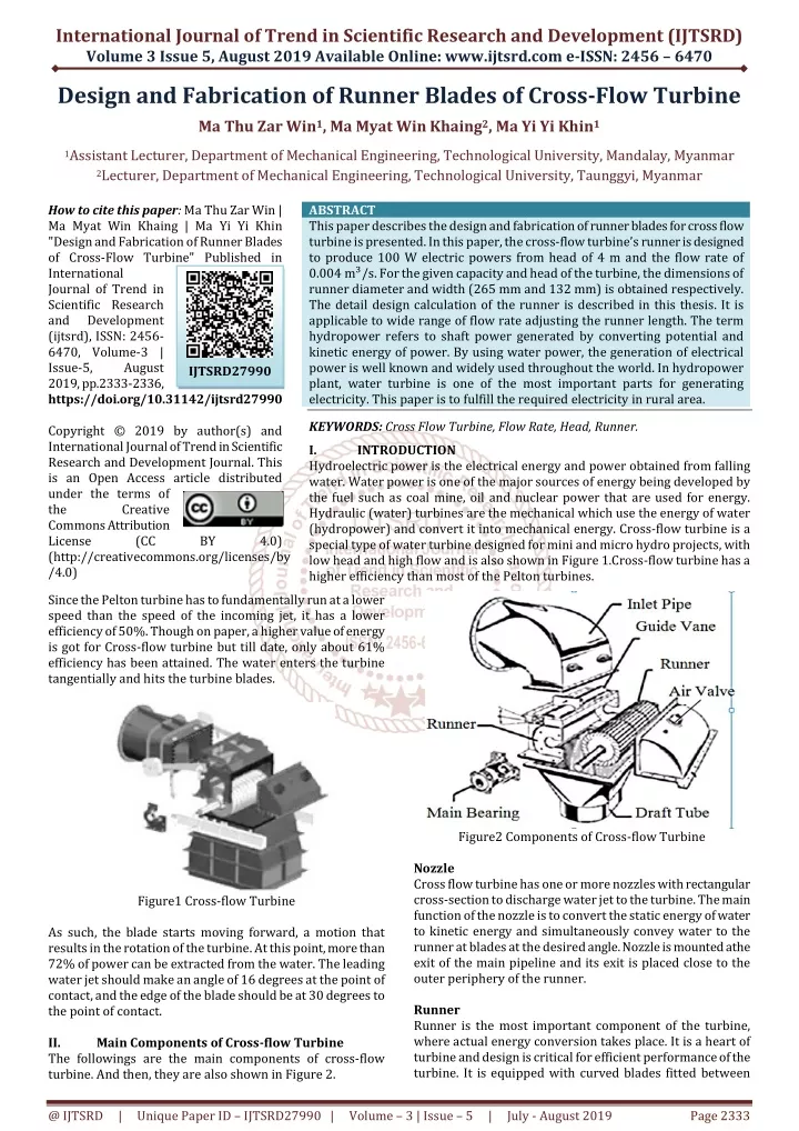
International Journal of Trend in Scientific Research and Development (IJTSRD) Volume 3 Issue 5, August 2019 Available Online: www.ijtsrd.com e-ISSN: 2456 – 6470 Design and Fabrication of Runner Blades of Cross-Flow Turbine Ma Thu Zar Win1, Ma Myat Win Khaing2, Ma Yi Yi Khin1 1Assistant Lecturer, Department of Mechanical Engineering, Technological University, Mandalay, Myanmar 2Lecturer, Department of Mechanical Engineering, Technological University, Taunggyi, Myanmar How to cite this paper: Ma Thu Zar Win | Ma Myat Win Khaing | Ma Yi Yi Khin "Design and Fabrication of Runner Blades of Cross-Flow Turbine" Published in International Journal of Trend in Scientific Research and Development (ijtsrd), ISSN: 2456- 6470, Volume-3 | Issue-5, August 2019, pp.2333-2336, https://doi.org/10.31142/ijtsrd27990 Copyright © 2019 by author(s) and International Journal of Trend in Scientific Research and Development Journal. This is an Open Access article distributed under the terms of the Creative Commons Attribution License (CC (http://creativecommons.org/licenses/by /4.0) Since the Pelton turbine has to fundamentally run at a lower speed than the speed of the incoming jet, it has a lower efficiency of 50%. Though on paper, a higher value of energy is got for Cross-flow turbine but till date, only about 61% efficiency has been attained. The water enters the turbine tangentially and hits the turbine blades. ABSTRACT This paper describes the design and fabrication of runner blades for cross flow turbine is presented. In this paper, the cross-flow turbine’s runner is designed to produce 100 W electric powers from head of 4 m and the flow rate of 0.004 m?/s. For the given capacity and head of the turbine, the dimensions of runner diameter and width (265 mm and 132 mm) is obtained respectively. The detail design calculation of the runner is described in this thesis. It is applicable to wide range of flow rate adjusting the runner length. The term hydropower refers to shaft power generated by converting potential and kinetic energy of power. By using water power, the generation of electrical power is well known and widely used throughout the world. In hydropower plant, water turbine is one of the most important parts for generating electricity. This paper is to fulfill the required electricity in rural area. KEYWORDS: Cross Flow Turbine, Flow Rate, Head, Runner. I. INTRODUCTION Hydroelectric power is the electrical energy and power obtained from falling water. Water power is one of the major sources of energy being developed by the fuel such as coal mine, oil and nuclear power that are used for energy. Hydraulic (water) turbines are the mechanical which use the energy of water (hydropower) and convert it into mechanical energy. Cross-flow turbine is a special type of water turbine designed for mini and micro hydro projects, with low head and high flow and is also shown in Figure 1.Cross-flow turbine has a higher efficiency than most of the Pelton turbines. IJTSRD27990 BY 4.0) Figure2 Components of Cross-flow Turbine Nozzle Cross flow turbine has one or more nozzles with rectangular cross-section to discharge water jet to the turbine. The main function of the nozzle is to convert the static energy of water to kinetic energy and simultaneously convey water to the runner at blades at the desired angle. Nozzle is mounted athe exit of the main pipeline and its exit is placed close to the outer periphery of the runner. Runner Runner is the most important component of the turbine, where actual energy conversion takes place. It is a heart of turbine and design is critical for efficient performance of the turbine. It is equipped with curved blades fitted between Figure1 Cross-flow Turbine As such, the blade starts moving forward, a motion that results in the rotation of the turbine. At this point, more than 72% of power can be extracted from the water. The leading water jet should make an angle of 16 degrees at the point of contact, and the edge of the blade should be at 30 degrees to the point of contact. II. Main Components of Cross-flow Turbine The followings are the main components of cross-flow turbine. And then, they are also shown in Figure 2. @ IJTSRD | Unique Paper ID – IJTSRD27990 | Volume – 3 | Issue – 5 | July - August 2019 Page 2333
International Journal of Trend in Scientific Research and Development (IJTSRD) @ www.ijtsrd.com eISSN: 2456-6470 runner discs. In the case of wider runner, the blades have multiple interposed by the supporting board. Runner may have up to 37 blades, depending upon the operating conditions. Blades The blades are form of circular blades which radially position at equal distance from each other in grooves machined depending on the size. The blades are fitted at the both sides into end plates and welded by a special method. This function is to change the direction of the incoming flow from the nozzle. Casing Casing prevents splashing of water and directs the water to the draft tube, if present. Casing, in case of reaction turbine, creates near vacuum conditions for mounting the draft tube. Shaft Shaft is an integral part of the runner. It transfers the torque generated by the turbine to the generator or alternator. Shaft should be designed correctly, so that it does not cause any hindrance to the flow of water to the second stage. Bearing The shaft is supported by bearings. Bearings reduce resistance to the rotation of the turbine. The main bearings of cross flow turbines are usually used with the standardized spherical roller bearing. Roller bearings have undeniable advantages in water turbines provided that the design of the bearing housing prevents any leakage and consideration occurring. Apart from an annual grease change the bearing requires no maintenance. Draft Tube Draft tube connects the turbine outlet to the tailrace. It is used to recover a major portion of the residual energy left in the water escaping out of the runner. Moreover, it permits the turbine to be set above tailrace without any appreciable loss in head. Air Valve Air valve is used to control water level in the housing. In case of turbine having a draft tube, the air inside the housing is swept out to create vacuum and a suction column rises in the draft tube. It is important to adjust the air valve correctly so that the right amount of air is present in the turbine chamber. Too much air would cause a decrease in suction head and hence a reduction in efficiency and too little air would cause drowning of the rotor, causing excessive drag and loss in efficiency. Guide Vanes Guide vanes direct the water and let it enter the runner smoothly, with minimum losses. In split cross flow turbine the admission of water into the runner is controlled by two guide vanes which divide the water flow. Both guide vanes can be adjusted independently and can be used as a shutoff valve or closing device if there is lower head. III. Design Theory Power Output The theoretical power output is an assumption of the energy of the site with aloe of the micro-hydro scheme. It can be calculated by using the site and volumetric flow rate. Following formula is true for the calculation of power output. P? = ηγQH = ηρgQH Where, P? = Power Output of the Turbine, W η = Overall Efficiency, % Q = Volume Flow Rate, m?/s ρ = Density of Water, kg/m? g = Gravity of Earth, m?/s H = Head, m Runner Outer Diameter The following steps are involved in the calculation of runner outer diameter: 1.Calculation of Runner rpm 2.Calculation of Water Jet Velocity 3.Calculation of Runner Tangential Velocity Calculation of runner rpm The runner rpm is calculated using the generator rpm and the speed ratio, 1500 N 1 2 Speed Ratio Calculation of water jet velocity The water tangential velocity is calculated using the head of the site; the coefficient C accounts for the roughness in the water bed. Following is the formula used: v Where, the coefficient upon the nozzle, c = 0.98 v?= Water Jet Velocity, m/s Calculation of runner tangential velocity First, the efficiency of the turbine is calculated as follows: 2 1 out P 3 c 2gH 1 γQv 4 2 c 2g P out 5 η = th P in This gives the following equation for efficiency: ψcosβ (1 1 η u 2 2 1 2c u )(cos α ) 1 β v 1 1 6 th v 1 In the above equation, assume β?= β? , differentiating with respect to u?/v? and then equating to zero, gives the ratio u?/v? for the maximum efficiency, which gives: cosα 1 1 Where, α?=angle of attack 1 u = the runner tangential velocity The following formula relates the runner rpm and runner tangential velocity: N 1 1 7 u 0.5v 1 πD u 8 60 @ IJTSRD | Unique Paper ID – IJTSRD27990 | Volume – 3 | Issue – 5 | July - August 2019 Page 2334
International Journal of Trend in Scientific Research and Development (IJTSRD) @ www.ijtsrd.com eISSN: 2456-6470 Where, Therefore, N=rotational speed, rpm The runner outer diameter and runner inner diameter are shown in Figure 3. D =the turbine outer diameter, m s 1 1 t 15 sinβ 1 Where, n =Number of blades t =Thickness of blade, m D?=Turbine’s outer diameter, m Radius of Blade Curvature The radius curvature of blade can be chosen from a circle whose center lies at the intersection of two perpendiculars, one to the direction of relative velocity v? and the other to the tangent to the inner periphery intersecting at (n) as shown in Figure 4. From triangle onP? and OmP?,OP?is common.Then, (On)? + (nP?)?= (Om)?+ (mP?)?- 2 (Om)(mP?)cos β? Om = R?,On = R? mP? = nP? = r (radius of blade-shape) Radius of circle of center pitch of blade-shape arc R?, 2 2 1 r Figure 3 Outer and Inner Diameter of Runner Runner Inlet Diameter The suggested result inner to outer diameter ratio for a cross flow turbine is 0.7(Aziz and Desai, 1991). Therefore: Runner Inner Diameter, 2 Length of Turbine Runner A standard procedure in determining the length of cross flow turbine is followed in banki technical paper, which involves the calculation of the product of the turbine diameter and breadth. With the turbine outer diameter already calculated, this product can then be used to calculate the length of the runner. The mechanical procedure is as follow: 144QN L Where, Q = Flow-rate of water, m?/s H = Head, m N = Revolution per minutes, rpm Thickness of Water Jet, 0.2D 0 Spacing of Blade, kD 1 Where, K = 0.087 (for most cases) 1 Radial Rim Width The radial rim width can be determined as the half of runner outer diameter and runner inner diameter difference. Diameter Inner Runner 1 a 2 (R R ) 16 D 9 0.7D 1 2R cosβ 1 1 When r? = 0.7r? and β?=30° 0.16D r 1 Therefore, the radius of pitch circle, 2 r 2 0 R = 0.733r? = 0.37 The blade pitchP?P? , 2ππ 2 1 2 17 R R D 0 1 10 862 0.98 0.087 2 9.81 H 0 P P 18 n s 11 1 s 12 1 1s =spacing of blade Figure 4 Curvature of Blade D =Runner outer diameter, m Shape of Runner Runner shape and dimensions are important in many types of turbines. The dimensions consist of the outer diameter and width of the runner as shown in Figure 5. D 13 2 Number of Blades Number of blades is the mechanical procedure presented in Banki technical paper. πD n 1 14 Figure 5 Runner t @ IJTSRD | Unique Paper ID – IJTSRD27990 | Volume – 3 | Issue – 5 | July - August 2019 Page 2335
International Journal of Trend in Scientific Research and Development (IJTSRD) @ www.ijtsrd.com eISSN: 2456-6470 The dimension of runner can be known from the velocity ratio. The velocity ratio, sometimes known as the peripheral coefficient or speed factor, is the ratio of the peripheral velocity of the runner at the nominal inlet diameter to the absolute velocity of water flow. IV. Runner Design Calculation of Cross Flow Turbine In considering the design of turbine, the hydraulic efficiency, the best speed for maximum efficiency, synchronous speed and runaway speed are required. The cross flow turbine is designed for 4m head and flow rate of 0.004 m?/s. The overall efficiency is assumed to be 65%. The angle of attack to the turbine is assumed to be 16 according to Banki Design and turbine’s runner rpm is 300 revolutions per min. Design Data, Effective head H=4 m Discharge Q=0.004 m?/s Overall efficiency η?=65 % Rotational Speed N=300 rpm Angle of attack α?=16°(assume Banki’s design) The results for runner design calculation are as below. Table I. Calculation Results for Runner Design Parameter Power Output, ???? Runner Outer Diameter, D stages and work is done two times in cross-flow turbine. Therefore, the cross-flow turbine has wide range application in terms of flow rate and head. This turbine can be built with two separate guide vanes to control the water. Efficiency of the turbine can vary with the flow by controlling the guide vanes. The simple design of this turbine allows easy manufacturing without the need for sophisticated facilities. In this thesis, cross-flow turbine is designed for 4 m of head and 0.004 m3/s of flow rate to generate 100 W. The attack angle at the runner is taken as 16° to get optimal efficiency. Cross-flow turbine’s runner design is calculated. The diameter of the runner is 265 mm and length is 132 mm. The numbers of blade are 18 depending on runner diameter. REFERENCES [1]Adam Harvey with Andy Brown, PriyanthaHettiarachi and Allen Inversion, 1998. “Micro-Hydro Design Manual”, A guide to small-scale water power scheme, Intermediate Technology Publications, London, UK. [2]C. AMockmore and Fred Nerryfield., February, 1949. “The Banki Water Turbine”, bulletin Series No.25, Oregon State College, Corballis, USA. [3]Kubota, SC 2140, “Cross-Flow Turbine”, Model: KC-FT. [4]Maung Aung ZawHtun, June, 2007. “Design of 75 kW Cross-flow Turbine for Micro-Hydropower Plant”. Results 100 W 265 mm [5]apan International Cooperation Agency, July 2003. “The Study on Introduction of Renewable Energies in Rural Areas in Myanmar”, Nippon Korea CO., Ltd., Japan. 1 185 mm 132 mm 39 mm 34 mm 23 mm 40 mm 18 Runner Inner Diameter, Length of Turbine Runner, L Radius of Blade Curvature, r Blade Pitch, D 2 [6]SeirokuSajiki, “Commercialization of Cross-Flow Hydraulic Turbines and Their Power Generating Systems”’ series No.68, No.2. Hitoshi Yamamoto., 1983. P P 1 2 Spacing of Blade, ?? Radial Rim Width, a Numbers of Blade [7]S. K Agrawal, “fluid Mechanics and Machinery”. ASTM A216 Carbon Steel Casting [8]http://www.british-hydro.org/mini-hydro. Material Used [9]https://www.Micro-Hydropower.net/turbines.html V. In this paper, different types of turbines are briefly discussed and the runner of a cross-flow (Banki) turbine is designed. Unlike the other turbines, water is passed through two Discussions and Conclusion [10]https://www.waterturbine.com [11]https://www.Ossberger.de5. <www.internationaljournalssrg.org/IJIE/2016/Special -Issuse/.../IJIE-ICEIET- P119.pdf> @ IJTSRD | Unique Paper ID – IJTSRD27990 | Volume – 3 | Issue – 5 | July - August 2019 Page 2336