Download
1 / 25
250 likes | 260 Views
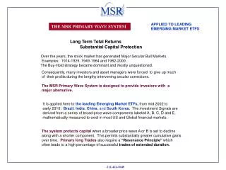
GigE for the MSR. Fred Kuhns fredk@arl.wustl.edu. Packet arrives with destination host on local network. Output port must map destination IP address to MAC address.

E N D
GigE for the MSR Fred Kuhns fredk@arl.wustl.edu
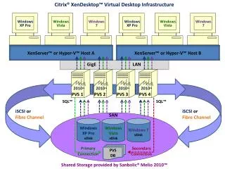
Packet arrives with destination host on local network. Output port must map destination IP address to MAC address. Use the Address Resolution Protocol to Map 192.168.204.2 to 08:00:20:7C:E3:25. Encapsulation datagram in Ethernet frame and send. Destination Addr: 192.168.204.2 IP hdr data Ethernet Forwarding Scenario 1 IP: 192.163.204.2 MAC: 08:00:20:7C:E3:25 IP: 192.163.204.3 MAC: 08:00:20:7C:F2:45 IP: 192.163.150.3 MAC: 08:00:20:54:6C:4A Host Host Host P3 Ethernet Switch Ethernet Switch MSR P1 P0 Port 1: IP: 192.163.204.2 MAC: 00:00:5E:04:00:01 Router Host P1 Port 0: IP: 192.163.204.4 MAC: 00:01:03:7C:23:03 Port 1: IP: 192.163.150.1 MAC: 00:01:03:7C:56:34 IP: 192.163.150.2 MAC: 00:40:33:A3:4C:04
Packet arrives with destination host NOT on locally attached network. Output port must send to the next hop router. Forwards to final destination host Next hop router IP address must be used in the ARP request: Map 192.168.204.4 to 00:01:03:7C:23:03. Encapsulate datagram in Ethernet frame and send. Destination Addr: 192.168.150.2 IP hdr data Ethernet Forwarding Scenario 2 IP: 192.163.204.2 MAC: 08:00:20:7C:E3:25 IP: 192.163.204.3 MAC: 08:00:20:7C:F2:45 IP: 192.163.150.3 MAC: 08:00:20:54:6C:4A Host Host Host P3 Ethernet Switch Ethernet Switch MSR P1 P0 Port 1: IP: 192.163.204.2 MAC: 00:00:5E:04:00:01 Router Host P1 Port 0: IP: 192.163.204.4 MAC: 00:01:03:7C:23:03 Port 1: IP: 192.163.150.1 MAC: 00:01:03:7C:56:34 IP: 192.163.150.2 MAC: 00:40:33:A3:4C:04
Ethernet Frame Format Destination (6 B) Destination Address cont. Ethernet Header Source Address - (6 B) Source Address cont. Ether Type (2 B) Version H-length TOS Total length Identification Flags Fragment offset IP Header TTL Protocol IP Header checksum IP Source Address IP Destination Address IP Datagram Transport Header
IP Encapsulation in Ethernet Frames • Ethernet frame size: 64 - 1518 Bytes • if type 1500, then IEEE frame, otherwise Ethernet V2. Ethernet Encapsulation, RFC 894 Pad (0-46) type 0800 dst address (6) src address (6) Data (46-1500) FCS (4) IEEE 803.2/802.2 encapsulation, RFC 1042 802.2 LLC/SNAP len (2) Pad (0-46) dst address (6) src address (6) Data (38 - 1492) FCS (4) 0 len 1500 802.2 LLC 802.2 SNAP DSAP AA SSAP AA ctl 03 Org Code 00 type 0800
ARP Frame Destination Address (6B) Source Address (6B) Ether Type (2B) Hardware Address Space (2B) Protocol Address Space (2B) Byte length of Hardware address = 6 (1B) Byte length of Protocol address = 4 (1B) Operation Code 1/2(2B) Hardware Address of Sender (6 B) Protocol Address of Sender (4 B) Hardware Address of Destination (6 B) Protocol Address of Destination (4 B)
ARP Message Formats ARP Message (28 Bytes for Request or Reply) Host A Eth <eth-B> Host A IP <ip-A> ARP Request Request (01) dst address ff:ff:ff:ff:ff:ff src address <eth-A> type 0806 has 0001 pas 0800 hl 6 pl 4 op 01 sha <eth-A> spa <ip-A> tha <??> tpa <ip-B> FCS xx pad 18 Byte Pad ARP Reply Reply (02) dst address <eth-A> src address <eth-B> type 806 has 1 pas 800 hl 6 pl 4 op 02 sha <eth-B> spa <ip-B> tha <eth-A> tpa <ip-A> FCS xx pad Host B Eth <eth-B> Host B IP <ip-A> FCS (4B) Ethernet Header (14 B) Ethernet Data - Pad with zeros to 46 Bytes Ethernet Frame with ARP Request/Reply - 64 Bytes
IP over ATM (rfc 791 and 2684) Version H-length TOS Total length Identification flags Fragment offset TTL protocol Header checksum IP Header Source Address Destination Address IP Datagram Options ?? IP data (transport header and transport data) AAL5 padding (0 - 40 bytes) AAL5 Trailer CPCS-UU (0) CPCS-UU (0) Length (IP packet + LLC/SNAP) CRC
D F M F 0 IP Header Fields (rfc 791) • Version - support IPv4 (4) • Header Length - Length in 32 bit words (>= 5) • TOS - • Total Length - Length of datagram in octets • Id - Assists in reassembling fragments • Flags - • Fragment Offset - Where fragment belongs, offset is in octets TOS Precedense Field: 111 - Network Control 110 - Internetwork Control 101 - Critic/ECP 100 - Flash Override 011 - Flash 010 - Immediate 001 - Priority 000 - Routine Remaining TOS Fields: D - 1 = Low delay T - 1 = High Throughput R - 1 = High Reliability Prec. D T R 0 0 DF - 1 = Don’t Fragment, MF - 1 = More Fragments
IP Header Fields • TTL - router must decrement, if 0 then discard packet • Protocol - UDP/TCP/ICMP/RSVP to name a few • Header Checksum - 16 bit one’s complement of the one’s complement sum of all 16 bit words in header • Source Address - Sending hosts IP address • Destination Address - Destination hosts IP address
plugins plugins FIPL FIPL IP proc IP proc Packet Routing Within MSR Ingress Egress • IP processing for FPX • Broadcast and Multicast destination address • IP options • ICMP messages • Packet not recognized WUGS Current VCI Support 1) 64 Ports (PN) 2) 16 sub-ports (SP) SPC SPC Ethernet: Base VC used for directly attached hosts, subports are for hext hop routers shim demux shim update shim update shim demux FPX FPX OutVC InVC Link Interface Link Interface add shim shim proc. rem shim FIPL ... ... out port + IntBase (64 ... 127) in port + IntBase (64 ... 127) From previous hop router or endstation Inbound VC = SPI + ExtBase 0 <= SPI <= 15 Currently support at most 4 Inbound VCs: One for Ethernet or Four for ATM ATM uses VCs as link layer address. Outbound VC = SPI + ExtBase 0 <= SPI<= 15 currently support at most 4
Endsystem, broadcast or multicast address Pkt VC = 50 VIN Table - 4 entries VC MyIP NhIP 50 MyIP0 0 51 MyIP0 NhIP0 52 MyIP1 NhIP1 53 MyIP2 NhIP2 To a next hop router NH #1 = Base + 1 = 51 NH #2 = Base + 2 = 52 NH #3 = Base + 3 = 53 GigE Link Interface Map multicast or broadcast to ethernet address If ARP table lookup fails, send ARP request to broadcast address, drop packet. No retries are made. Send to pkt->dst if bcast or mcast map to eaddr else resolve w/ARP ARP Table (M Entries) IP MAC No ARP entry aging! MAC1 IP1 ... ... IP Header Ethernet MACM IPM data IP Header From FPX/SPC AAL5 trailer data To Next Hop or Endstation Add Ethernet header using the derived destination address and out source address. Protocol is IP. if VC != 50, Lookup VC in VIN table returns IP used for ARP lookup (support N = 4) Software creates VIN table at boot time by writing to interface.
Ethernet Assigned Numbers • RFC1700 obsoleted by online database at IANA: • http://www.iana.org/assignments/ethernet-numbers • Ethernet Address - 6 octets: • 3 high-order octets = Organizationally Unique Identifier (OUI) • 3 low-order octets = the interface number • Multicast bit = lsb of the MSB (xxxx xxx1) • first byte odd => multicast or broadcast • first byte even => unicast address • multicast address = ((OUI | 0x0100) << 24) & Group_ID • Ethernet Broadcast: FF:FF:FF:FF:FF:FF
IP and Ethernet Multicast • IANA has allocated address block with OUI = 00:00:5E • Used for unicast addresses for ”IETF standard track protocols “ • Half of Multicast addresses reserved for IP, remaining for “special use”. Leaves 23 bits for multicast addresses: • 01:00:5E:00:00:00 to 01:00:5E:7F:FF:FF • Could use this block for our interface, see ethernet numbers • IP Multicast • Class D address, 0xE0000000 + 28 Bit Group ID • 224.0.0.0 to 239.255.255.255 (0xE0000000 - 0xEFFFFFFF) • IP to Ethernet Mapping • RFC1112 - Host Extensions for IP Multicasting • Non-unique mapping: 28 bit IP group to 23 bit Ethernet group • 32 IP multicast groups per mapped ethernet multicast address.
23 bits Multicast: IP to Ethernet Mappings • Network Byte Ordering, Internet Standard Bit order: (Big-Endian) Multicast Bit Internet Bit 0 MSB 24 LSB 47 0000 0001 0000 0000 0101 1110 0xxx xxxx xxxx xxxx xxxx xxxx Block of Ethernet Multicast Address 0 8 1110 xxxx xxxx xxxx xxxx xxxx xxxx xxxx msb lsb Class D (Multicast) LSB Not Used in IP to Ethernet Mapping
IP Broadcast • No Direct Impact on GigE Interface • IP Broadcast : default, we will not forward directed broadcasts. • limited versus: • {-1, -1}. Must not be forwarded, Destination address only • Directed broadcast: • {Network-Number, -1}, destination address only. • Subnet Directed Broadcast: • {Network-Number, Subnet-Number, -1} • Directed Broadcast to all subnets: • {Network-Number, -1, -1}
Unicast - If we use the IANA Block Multicast Bit set to 0 0 MSB 23 LSB 47 0000 0000 0000 0000 0101 1110 0000 0100 xxxx xxxx xxxx xxxx IANA Block of Ethernet Addresses 16 bits ARL Interface Number
to FPX/SPC Base VC GigE Link Interface ARP Table (M Entries) receive ethernet frame: eth if (eth->type == ARP) if (eth->arp->has != Ethernet/0001) Drop Frame if (eth->arp->pas != IP/0800) Drop Frame update {eth->arp->spa, eth->arp->sha} in ARP table if (eth->arp->tpa NOT in {MyIP0, MyIP1, MyIP2}) Drop Frame // target IP not ours if (eth->arp->op == Request/01) { swap source and target ARP info set operation to Reply set ether header src and dst address send reply } // Already handled eth->arp->op == Reply/02 // when updated cache above else if (eth->type == IPv4) remove ethernet header, padding and CRC add AAL5 trailer and required padding break into cells and send on default Base VC else Error, drop packet *Unicast MAC address filtering IP MAC MAC1 IP1 ... ... MACM IPM Ethernet IP Header IP Header From Next Hop or Endstation data To FPX/SPC data AAL5 trailer
Notes • Packet Received on ATM interface: • If received on Base_VC (i.e. 50) then • map IP destination (ip->dst_addr) to ethernet representation. • Unicast uses ARP table, multicast and broadcast use appropriate mapping. • Otherwise, • lookup VC in VIN table: Table entry index = RX_VC - Base_VC. • ARP the resulting Next Hop IP address. • This permits a simple mechanism for “tunneling” traffic to a gateway. This allows us to support directed broadcast and provides a convenient mechanism for testing. • Packet received on Ethernet interface: • if IPv4 then send all (unicast, multicast and broadcast) to input port processor on the Base_VC (i.e. 50)
ARP Table IP Ethernet VIN Table Entry Number Prefix Mask Local IP Address Next Hop IP Address IP0,0 Ether0,0 Net 0 ... ... 0 Mask0 MyIP0 NH0 IP0,255 Ether0,255 1 Mask1 MyIP1 NH1 IP1,0 Ether1,0 2 Mask2 MyIP2 NH2 Net 1 ... ... IP1,255 Ether1,255 IP2,0 Ether2,0 Net 2 ... ... IP2,255 Ether2,255 ARP Cache • IP Address = Network_Prefix.Host or simply Net.Host • Assume a prefix length of at least 24 bits, leaves 8 bits for the host • An interface can have at most 3 unique IP addresses • Interface may communicate with at most 256 hosts per network • Implement ARP cache as a table with 768 entries (3 * 256) • See next slide Net 0 = Mask0 & MyIP0 Net 1 = Mask1 & MyIP1 Net 2 = Mask2 & MyIP2
Implementing the ARP Table VIN Table ‘get next packet’: // received frame from ATM interface if (RX_VC == Base_VC) ipdst = ip->dst_addr; else ipdst = VIN_Table[RX_VC- Base_VC].NextHop // ipdst == IP Address of host we must send packet to // determine network for (i = 0; i < 3; i++) { if ((ipdst & Maski) == (MyIPi & Maski)) { index = (i << 8) | (ip->dst_addr & ~Maski) break; } if i == 3 ; drop packet, goto get next packet // i corresponds to the Network Number (0 - 2) if (ArpTable[index].EtherAddress != 00:00:00:00:00:00) { construct ethernet frame send packet goto ‘get next packet’ } else { send ARP Request for ipdst drop packet, goto ‘get next packet’} Entry Number Prefix Mask Local IP Address Next Hop IP Address 0 Mask0 MyIP0 NH0 1 Mask1 MyIP1 NH1 2 Mask2 MyIP2 NH2 ARP Table IP Ethernet IP0,0 Ether0,0 ... ... IP0,255 Ether0,255 index IP1,0 Ether1,0 ... ... IP1,255 Ether1,255 IP2,0 Ether2,0 ... ... IP2,255 Ether2,255 don’t need to store IP address
Notes and Issues • GigE Control Interface for Software configuration. • Reset interface to defaults • Clear ARP cache • Read ARP table • Read VIN table • Read ethernet address • set VIN table entries and other registers • Set BASE VC (currently 50) • Set Entries in the VIN table • Add static ARP entries??
Notes and Issues • Comprehensive testing scenarios need defining • verify multicast and broadcast • VC to control line card
References • RFC 1122 - Requirements for Internet Hosts • Must send and receive using RFC-894 - compliant • Should receive RFC-1042 mixed with RFC-894 - we do not • May send using RFC-1042 - we do not • Must use ARP • Must flush out-of-date ARP cache entries - not compliant • Must prevent ARP floods - we only try once • Should have configurable ARP cache timeout - no • Should save at least one (latest) unresolved (by ARP) packet - no • Must report broadcasts to IP layer - compliant • IP layer Must pass TOS to link layer - via the header • Must Not report no ARP entry as “destination unreachable” - compliant
References • RFC-826 : Address Resolution Protocol • Maps <protocol, address> to 48 bit Ethernet address • our processing differs in minor ways • RFC 1700 : Assigned Numbers • Ethertype values defined by RFC 1700 • IP to ethernet multicast address mapping defined • RFC-1812 : Requirements for IPv4 Routers • Must not believe ARP reply if contains multicast or broadcast address - not compliant • Must be compliant with RFC 1122 - Partial • Support Ethernet V2 only • RFC 894: IP encapsulation in Ethernet V2 - Supported • RFC 1042: IP encapsulation in 802.3 frames - Not Supported