Download
1 / 9
140 likes | 327 Views
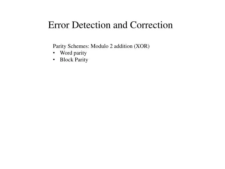
Parity Schemes: Modulo 2 addition (XOR) Word parity Block Parity. Error Detection and Correction. CRC Error Correction.

E N D
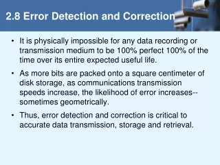
Parity Schemes: Modulo 2 addition (XOR) • Word parity • Block Parity Error Detection and Correction
CRC Error Correction CRC error correction schemes are mechanized using the binary symbol alphabet {0,1} and modulo 2 arithmetic. However the math behind it is applicable with any symbol alphabet and any legitimate algebra. We will explore the method using normal, decimal arithmetic. Consider a message: [mN-1,mN-2, m1,m0] where the miare symbols selected from the symbol alphabet M = {0,1,2,3, ..,8,9}. The number of symbols in the alphabet is x = 10, each symbol carries 3.32 bits of information. If we were to see the actual digits written out, we would intuitively associate a value with the message, represented by the polynomial: M(x) = mN-1xN-1 + mN-2 xN-2 + .. + m1x1 + m0x0 We are going to append two check digits to the message, [c1,c0]. The polynomial representing the check digits is of order C = 2: C(x) = c1x1 + c0x0
The Message digits must be shifted to the left to make room for the check digits, do the final data word will be represented by the polynomial: D(x) = xcM(x) + C(x) =M’(x) + C(x) Here’s the trick. We want to pick C(x) such that D(x) represents a number which is evenly divisible by some other number, G, called the generator, represented by the “generator polynomial” G(x). Stated mathematically: Where R0(x) =0 is the remainder polynomial after division. Consider for a moment performing the division with the check digits set to zero: Where R1(x) is the remainder polynomial after division. If we set C(x) = G(x) – R1(x), then we can write . . .
And we have zero remainder, as desired. When the message is received at the destination, it is divided by the generator, and if the remainder is zero, we may be certain that a single digit error did not occur. If the generator is judiciously chosen, when an error occurs, the remainder will uniquely identify which digit was corrupted. Consideration of the number of check digits There must be a unique remainder for every possible error that can occur. In a binary code (x = 2), there is one possible error for each digit in D(x) . Since the remainder must be less than G, it is clear that G > N + C. Since the order of G must be equal to the order of C(x) i.e. C, the maximum value for G is xC-1. Thus or,
Example We’ll consider an example using decimal arithmetic. We will construct a message of 5 digits. For simplicity, we will consider the only possible transmission errors to consist of increasing or decreasing each digit by one, so two possible errors per digit in the message (including check digits), so G > 2(N+C), and G < 10C . Thus, for this scheme: or, So C = 2 digits will work, and G > 14. Lets try G = 17 (prime numbers usually work well). We need to verify that each possible error creates a unique remainder, so lets pick a typical message, determine the check digits, introduce each possible error, and see if we get a unique remainder. If we don’t, we have to try another generator.
Verification The remainders for each possible error are: These are all unique, so we gave a good generator. The sorted remainders, and their corresponding corrections are:
Modulo 2 Division 1 0 1 0 0 1 0 1 0 0 1 0 1 1 0 1 1 0 1 0 1 0 1 1 0 1 0 0 1 0 1 0 0 0 0 0 0 0 1 0 0 0 0 1 0 1 1 0 0 0 0 0 0 0 0 0 0 0 0 1 0 0 0 0 1 0 1 1 0 1 0 0 0 0 0 1 1 1 0 0 0 0 1 1 0 1 1 1 1 0 0 0 0 0 0 0 0 1 1 0 0 0 0 0 0 1 0 0 0 1 0 0 1 0 1 0 0 0 0 1 0 1 x 0 1 1 0 0 x x 1 0 1 0 1 1 x 1 x 0 x 0 1 1 x 0 x 0 x 1 x x x 1 x x 1 x 0 x x x x 0 1 x x 0 x x x x x x x 0 0 1 0 0 0 1 1 0 + 0 0 0 0 0 0 0 0 0 0 1 0 0 0 1 1 0 0 0 0 0 0 0 0 0 1 0 0 0 1 1 0 1 0 0 1 0 1 0 0 0 1 1 0 0 0 0 0 0 0 0 0 1 1 0 0 + + x
Manipulate the Structure: x + + After 5 Shifts Initial State Final State Flip Over Data 0 0 1 1 + + 0 1 x 1 0 x 0 1 1 x 0 x 1 x 1 0 0 0 1 1 0 0 1 0 1 1 0 0 0 0 0 1 1 x 0 0 x 1 x x x x 0 1 x x 1 x x x x 0 Flip Again Data + + 0 1 1 0 0 1 0 0 1 0 (1)
Notes on Generator Choice • Generator must have one more digit than Check Digits. • Generator must be of the form: 1 X X … X 1