Download
1 / 162
1.64k likes | 1.88k Views
Programable Logic Controllers RBT-235-SC61. WELCOME!. Instructor: Dan Wolf http://web.acd.ccac.edu/~dwolf/ 1/20/2014. Week #1 - The PLC Demo. Home Assignments: 1. Complete and turn in the Student Information Sheet 2. Read the textbook sections as stated in the syllabus Lab Assignment:

E N D
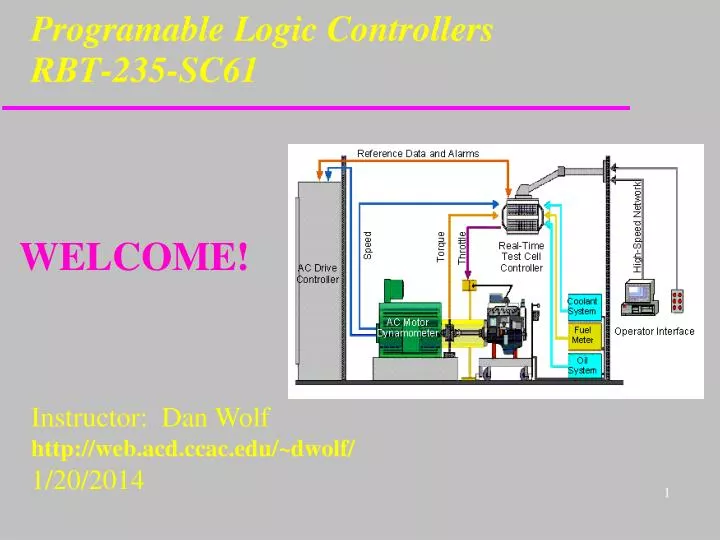
Programable Logic ControllersRBT-235-SC61 WELCOME! Instructor: Dan Wolf http://web.acd.ccac.edu/~dwolf/ 1/20/2014
Week #1 - The PLC Demo Home Assignments: 1. Complete and turn in the Student Information Sheet 2. Read the textbook sections as stated in the syllabus Lab Assignment: Module 1 – Intro and Wiring
Student Information 1. Name 2. Student ID Number 3. Phone Number 4. Alternate Phone Number 5. Do you have easy access to a PC? 6. What other programming classes have you taken? 7.a.Do you have any hardware or electronics experience? 7.b. What areas? 8.a. What is your major? 8.b. Is your major a 2 or 4 year program? 8.c. What is your expected graduation date? 9. Your EMAIL address
Introductions • Introduction to the Instructor • Student Introductions a) Name b) Where do you work or what is your degree? c) Why are you taking this class?
Administrative Information 1. Introductions 2. Syllabus a. Contact Information b. Grading 2. Questions? 3. Beware of the “Wall”
RBT-235: Course Introduction A course providing a working knowledge of programmable logic controllers (PLCs). Topics include terminology, basic and advanced relay logic programming, and connection and control of input/output devices. Emphasis is placed on interfacing, operating, and programming a wide range of robotic and industrial automation devices. Prerequisites: None
Maximize Your Lab Time Read the lab work prior to each class Do not get behind in the labs You will need the entire scheduled lab time each week
Budgeting Your Time The college expects you to spend three home study hours for each hour in the classroom. This course will require 3 * 3 = 9 hours of home study each week. This is a technical / programming course. Nine hours is a good estimate.
Assignment #1 Questions to ask of two other students: 1) Name 2) Degree 3) Name of Pet 4) Employment 5) What do you want to learn from this class?
What is a PLC? As defined by the National Electrical Manufacturers Association (NEMA), a Programmable Logic Controller is: "a digitally operating electronic apparatus which uses a programmable memory for the internal storage of instructions for implementing specific functions, such as logic, sequencing, timing, counting and arithmetic, to controlthrough digital or analog input/output, various types of machines or process". In other words, it is a generic, computer controlled device that can be used to control a process such as required in a a factory manufacturing environment or a Disney fun ride.
Pushbuttons Selector Switches Limit Switches Level Switches Photoelectric Sensors Proximity Sensors Motor Starter Contacts Relay Contacts Thumbwheel Switches 120/230 VAC 24 VDC Sourcing Sinking Input Devices
Valves Motor Starters Solenoids Control Relays Alarms Lights Fans Horns Relays 120 VAC/VDC 240 VAC 24 VAC/VDC Triac 120/230 VAC Transistor MOSFET 24 VDC Output Devices
START Housekeeping Input Scan Internal checks on memory, speed and operation. Service any communication requests, etc. The status of external inputs (terminal block voltage) is written to the Input image (“Input file”). Output Scan ProgramScan The Output Image data is transferred to the external output circuits, turning the output devices ON or OFF. Each ladder rung is scanned using the data in the Input file. The resulting status (Logic being solved) is written to the Output file (“Output Image”). PLC Operating Cycle
Solenoid 2 Solenoid 1 Motor Ingredient A Ingredient B Sensor 1 Sensor 2 Solenoid 3 Typical PLC Application
Solenoid 1 On = Sol 3 is off, and Motor is off, and Sensor 2 is off, and Auto Switch is on Off = Sol 3 is on, or Motor is on, or Sensor 2 is on Solenoid 2 On = Sol 3 is off, and Motor is off, and Sensor 2 is on Off = Sol 3 is on, or Motor is on, or Sensor 1 is on Motor On = Sensor 1 is on, and Solenoid 2 is off, and Solenoid 1 is off Off = Solenoid 3 on Solenoid 3 On = Sol 1 is off, and Sol 2 is off, and Motor has run for 30 sec. Off = Solenoid 3 has been on for 60 sec. Solenoid 2 Solenoid 1 Motor Ingredient A Ingredient B Sensor 1 Sensor 2 Solenoid 3 Operation of Mixer (Sequence of Control)
Basic Electric Refresher E = I * R E = Voltage Potential I = Current Flow R = Resistance (load) Current (I) always flows in the direction from the highest voltage to the lower voltage(s).
Wiring Practice for Tonight Do not apply power until I check your circuit!
Week #2 - Wiring & PLC Intro Home Assignments: 1. Informal Lab Material: Turn in lab samples 2. Read the textbook sections as stated in the syllabus Lab Assignment: Module 1
Logicals – Conventional Definitions • AND: If A and B are High Then F = High • OR: If A or B is High Then F = High • XOR: If A or B is High (but not both) Then F = High • NOT: If A is High then F = Low If A is Low Then F = High
Logicals – Switch Equivalents AND Gate OR Gate
Logicals – Switch Equivalents XOR Gate NOT Logic
Programming PLC’s The purpose of a PLC Program is to control the state of PLC outputs based on the current condition of PLC Inputs Different PLC’s support different languages, but the most popular PLC language is know as “Ladder Logic”. PLC Ladder Logic purposely resembles Relay Logic
Relay Logic versus Ladder Logic Relay Logic is an electrical circuit. Relay Logic Ladder Logic is a logic circuit not an electrical circuit. It establishes an output based on logic continuity. Ladder Logic Examine ON instruction: checks for ON state, does not care about NO or NC state
Ladder Logic Concepts Read / Conditional Instructions Write / Control Instructions | | ( ) Start (Rung #1) | | |/| ( ) | | |/| | | ( ) | | |/| ( ) | | | | |/| ( ) End (Rung #5)
Ladder Logic Concepts |/| | | ( ) F T F No Logical Continuity |/| |/| ( ) T T T Logical Continuity Read / Conditional Instructions Write / Control Instructions
On I/4 I/5 O/0 | | | | ( ) T T T Logical Continuity Logical AND Construction IF input 4AND input 5 have power THEN energize output 0
Logical OR Construction On T I/4 O/0 | | ( ) Logical Continuity I/5 F | | On F I/4 O/0 | | ( ) Logical Continuity I/5 T | | IF input 4OR input 5 have power THEN energize output 0
Complex Construction O/0 I/4 I/0 I/1 I/9 I/10 ( ) |/| | | | | | | | | I/5 I/1 I/7 I/8 | | |/| |/| |/| I/2 I/3 | | | | I/11 I/1 |/| | |
SOL2 PB1 LS1 PB2 LS1 CR3 LS3 CR Inputs Outputs M1 LS4 CR3 B/0 |/| I/4 O/0 I/6 |/| Programmable Logic Controller | | | | ( ) I/7 I/5 B/0 | | | | ( ) I/8 | | O/1 I/9 ( ) | | Relay Logic vs. PLC & Ladder Logic
SOL2 PB1 LS1 I/4 I/6 O/0 PB2 LS1 CR3 | | | | ( ) LS3 I/8 I/7 I/5 B/0 | | | | ( ) I/9 M1 LS4 CR3 | | | | B/0 |/| |/| O/1 ( ) Relay Logic to Ladder Logic INPUT Address Assignment: PB1- I/4 PB2- I/5 LS1- I/6 LS2- I/7 LS3- I/8 LS4- I/9 OUTPUT Address Assignment: SOL2- O/0 M1- O/1
Relay Logic versus Ladder Logic Relay Logic is an electrical circuit. Relay Logic Ladder Logic is a logic circuit not an electrical circuit. It establishes an output based on logic continuity. Ladder Logic Examine ON instruction: checks for ON state, does not care about NO or NC state
Helpful Hints on the PLC Syntax There are two (approximate) PLC identifier formats: • The syntax for the Inputs and Outputs are similar to each other. O:0.0/4I:0.0/3 • The syntax for the Binary, Counters, and Timers are similar to each other. B3:1/12T4:0/ENC5:0/CU The two formats are confusingly similar: • The colon “:” after the I/O in format #1 is not used in format #2 • The period “.” in format #1 appears to be replaced by a colon “:” in format #2
The Project Planning Sheet The Project Planning Sheet should be completed before you begin wiring or before you start the RSLogix program. • Description of the Requirements • Inputs • Outputs • Wiring Diagram • Ladder Diagram
The End Thank You !
Week #3 – PLC Demo & Try-out Home Assignments: • Informal Lab Material • Mini-Quiz 2. Read the textbook sections as stated in the syllabus Lab Assignment: Module 1
PLC Demo Turn your PC on and follow your instructor throughout the demonstration.
PLC Programming Process • Go Offline • Select the User tab • Drag a control from the User tab onto the rung. The red link squares will turn green when you approach them. Release the mouse button when the intended link spot is green. • Double-left click the control to add or change the address or parameter. • Click the Verify Project button to check your syntax
PLC Control Drag Operation Green link during a control drag operation.
RSLogix Run Procedure Summary of steps to run RSLogix: • Load RSLinx. Configure drivers as needed. • Minimize RSLinx • Load RSLogix • Load Program from disk or start new program. • Verify Program • Download to PLC • Go Online
Project Phases • Requirements Phase is based on “What to build” • Design Phase is based on “How to build it” • Implementation Phase is based on “Now is the time to build things” • Test Phase is based on “Prove that you have built the correct thing AND prove that it works correctly”.
RSLogix 1500 Instruction Set Help Start RSLogix 1500 Help | SLC Instruction Help