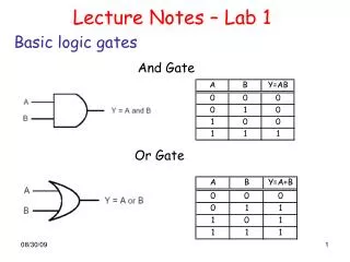
Download
1 / 42
420 likes | 430 Views
Basic Digital Logic. Chapter 2. Outlines. Basic Digital Logic Gates Two types of digital logic circuits Combinational logic circuits Sequential logic circuits Combinational logic circuit design Using sum of product Using product of sum Karnaugh map: Minimization of logic circuits

E N D
Basic Digital Logic Chapter 2 Basic Digital Logic
Outlines • Basic Digital Logic Gates • Two types of digital logic circuits • Combinational logic circuits • Sequential logic circuits • Combinational logic circuit design • Using sum of product • Using product of sum • Karnaugh map: Minimization of logic circuits • Without don’t care term • With don’t care term • Construction from smaller components • Sequential logic circuit Basic Digital Logic
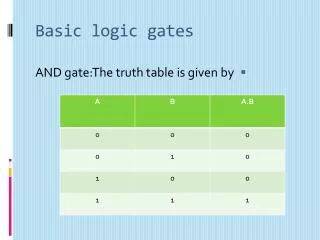
B A A B A Switches • Abstraction of building block of digital computers • Basic logic functions • AND • OR • NOT Basic Digital Logic
Basic Digital Logic Gates NOT gate AND gate OR gate XOR gate NAND gate NOR gate XNOR gate Basic Digital Logic
Combinational Logic Circuit Sequential Logic Circuit Two types of digital logic circuits • Combinational logic circuits • Output depends only on its input at that time. • Sequential logic circuits • Output depends both on • its previous output and • its input at that time Basic Digital Logic
Combinational Logic Circuit Basic Digital Logic
How to design a combinational logic circuit • Decide how to encode input and output in 0 and 1 • Describe each bit of the output in term of input • Truth table • Logical function • Construct a logic circuit from the logical function Basic Digital Logic
Truth table and logical function out = f (in1, in2, …) Basic Digital Logic
Boolean Logic • Basic Boolean operations • AND: X Y, X &Y, X Y, X Y • OR: X Y, X + Y • NOT: ~X, X’, X • Any Boolean expressions can be described in: • Disjunctive normal form (DNF) /sum of product • Conjunctive normal form (CNF) / product of sum Basic Digital Logic
Example: Exclusive OR (XOR) • output = X Y + XY Basic Digital Logic
Construct Sum of Products • Find out all conditions when the function is true • X Y = T(1) when • X=0, Y=1 => X Y =1 • X=1, Y=0 => XY = 1 • OR the conditions • X Y + XY minterm Sum of products Basic Digital Logic
Exclusive OR (XOR): Sum of products • output =X Y +XY X output Y Basic Digital Logic
Construct Product of Sums • Find out all conditions when the negation of the function is true • X Y = F(0) when • X=0, Y=0 => X + Y = 0 • X=1, Y=1 =>X +Y = 0 • AND the conditions • ( X + Y )(X +Y) maxterm Product of sum Basic Digital Logic
Exclusive OR (XOR) • output = ( X + Y )(X +Y ) X output Y Basic Digital Logic
Karnaugh Map (K-map) Basic Digital Logic
2-variable K-map Basic Digital Logic
3-variable K-map Basic Digital Logic
4-variable K-map Basic Digital Logic
Full Adder Full adder A B Ci S Co Basic Digital Logic
S=A’B’C+A’BC’+ABC+AB’C’ Full Adder Co=AB+BC+AC Basic Digital Logic
Encoder A3 Encoder X1 A2 A1 X0 A0 Basic Digital Logic
Encoder X1 = A1A0 Basic Digital Logic
Encoder X0 = A1+A3 Basic Digital Logic
2 - 4 decoder b3 b2 b1 b0 a1 a0 Decoder • If a1 a0 is a binary i, • bi is 1and • bj is 0 whenji. Basic Digital Logic
a1 b3 a0 b2 b1 b0 Decoder b3 = a1 a0 b2 = a1a0 b1 =a1 a0 b0 =a1a0 Basic Digital Logic
Multiplexor 2-1 multiplexor D1 D0 x S X = Ds Basic Digital Logic
Multiplexor X = S D0 + S D1 Basic Digital Logic
D1 D0 S X Multiplexor X = S D0 + S D1 Basic Digital Logic
Construction from Smaller Components Basic Digital Logic
C S1 S0 Co S Co S FA1 FA0 A B Ci A B Ci A1 B1 A0 B0 Ci=0 2-bit Full Adder 1 1 A1 A0 0 1 + B1 B0 + 1 0 0C S1 S0 2-bit full adder Basic Digital Logic
2 2 2 2 2 2 4-bit Full Adder 1 0 1 1 0 1 1 1 + 1 0 0 1 0 A1 A0 B1 B0 + C S1 S0 C S1 S0 Co S Co S 2FA1 2FA0 A B Ci A B Ci A1 B1 A0 B0 Ci=0 4-bit full adder Basic Digital Logic
Sequential Circuit Basic Digital Logic
Falling edge Rising edge clock cycle time / clock period Clock Signal oscillating between 0 and 1 Edge-triggered clocking The state of the sequential circuits changes on the clock edge. Basic Digital Logic
Types of sequential circuits • Synchronous circuits • With clock • Use in digital computers • Asynchronous circuits • Without clock Basic Digital Logic
Q Q 0 1 1 R R 0 0 1 1 0 Q’ Q’ S S 0 1 1 0 reset set Q 0 Q 1/0 1 R ? R 0/1 ? 1/0 ? Q’ Q’ S 0/1 S 0 ? hold 1 unstable SR Latch Basic Digital Logic
0 0 0 0 C C C C Q0 Q0 Q Q Q Q Q0 Q0 Q0 Q0 Q Q Q Q 0 1 D D D D 0 0 1 1 1 0 0 1 0 0 Q0 0 C D Q C=0 hold data C=1 load data 0 1 0 1 D Latch Basic Digital Logic
QD xD xx QQ D C Q Q D C Q Q D latch D latch D latch D latch Q Q Q Q D C D C D C D C D latch D latch D latch D latch Q Q Q Q D C D C D C D C 10 01 xx xx xD DD D C Q Q D C Q Q 00 11 C D Q C=1 0 load data D Flip-flop Basic Digital Logic
Registers D7 D6 D5 D4 D3 D2 D1 D0 clk D flip-flop D flip-flop D flip-flop D flip-flop D flip-flop D flip-flop D flip-flop D flip-flop O7 O6 O5 O4 O3 O2 O1 O0 Hold time C D Q 8 8 8-bit REGISTER Set-up time Din Dout clk Basic Digital Logic
Register Files n-1 n-2 0 n-2n decoder Register number n Write n-1 MUX Register n-1 8 Datain Dataout 8 Register n-2 . . . Register 0 Basic Digital Logic
Finite State Machines Next-state function (Combinational) Current State (registers) Output function (Combinational) Outputs Inputs Basic Digital Logic
a b clk D Q Q D Q Q clk a b Counter 0 -> 3 A = a b B =b Basic Digital Logic
D Q Q D Q Q R clk a b Counter with reset a b R clk A = R (a b) B = Rb Basic Digital Logic