Download
1 / 24
240 likes | 350 Views
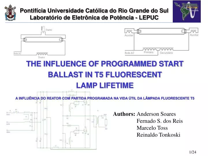
THE INFLUENCE OF PROGRAMMED START BALLAST IN T5 FLUORESCENT LAMP LIFETIME A INFLUÊNCIA DO REATOR COM PARTIDA PROGRAMADA NA VIDA ÚTIL DA LÂMPADA FLUORESCENTE T5. Authors: Anderson Soares Fernado S. dos Reis Marcelo Toss Reinaldo Tonkoski.

E N D
THE INFLUENCE OF PROGRAMMED START BALLAST IN T5 FLUORESCENT LAMP LIFETIME A INFLUÊNCIA DO REATOR COM PARTIDA PROGRAMADA NA VIDA ÚTIL DA LÂMPADA FLUORESCENTE T5 Authors: Anderson Soares Fernado S. dos Reis Marcelo Toss Reinaldo Tonkoski
THE INFLUENCE OF PROGRAMMED START BALLAST • IN T5 FLUORESCENT LAMP LIFETIME • Introduction • T5 fluorescent lamps, characteristics • Proposed topology • Simulation results • Experimental results • Rapid cycle test for T5 fluorescent lamps • Discussion • Conclusion • References
INTRODUCTION • In the last years, it have had an evolution in use of the more efficient illuminating systems, as example: to substitute fluorescent lamps by incandescent lamps, the use of electronic ballast in place of magnetic ballast, the use of more efficient fixtures and lamps. • Hanover Fair in 1995, great European manufacturers had presented the T5 a new fluorescent lamp with less diameter, shorter, more efficient and developed for to be successor of T8 [Gvén]. • This work presents analysis, development of an electronic ballast with voltage preheating for one 28W/T5 fluorescent lamp and rapid cycle test to determine the rated lifetime of lamp with the proposed electronic ballast.
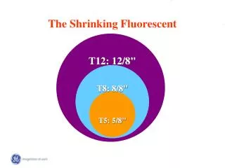
T5 T8 T10 T12 • T5 FLUORESCENT LAMPS – Characteristics • Less diameter 16mm (T5) to 26mm (T8), 40%; • Less lengths 1149mm (28W) to 1200mm (32W); • Lamp efficacy up to 104 lm/W • (10% compared T8); • Maximum light output at 35°C (25°C T8); • Low mercury dose; • Constant lumen level during lamp life (92% at 10.000 hours); • High frequency operation (no flicker); • More expensive (approximately 2.5 x T8); Fig. 01 – Fluorescent lamps, evolution.
T5 FLUORESCENT LAMPS – Characteristics • For a long lifetime and a stable light output, the electronic ballast should fulfill the strict requirements for preheating and steady state operation, as following [Davis]: • Preheating Operation • The filament should be first heated to an optimum temperature (about 1000K). • During filament preheating, the voltage across the lamp should be kept as low as possible. • Only after the filament’s optimum temperature is reached, the voltage of the lamp should rise to the ignition level. • Steady State Operation • Once the lamp is ignited, the ballast should behave as a current source to ensure stable operation. • The crest factor of the lamp’s current should not exceed 1.7.
PROPOSED TOPOLOGY • Selection of a preheating method depends on the types of filaments and on time available for ignition lamps [Chin]. Two fundamentally different drivers could be used for filament preheating [Davis][Chin]: a current source or a voltage source. • Current Source Filament Preheating • Disadvantages: • The filaments are placed inside the LC resonant filter, resulting in excessive lamp voltage during preheating and excessive filament current during runtime [Davis]. • After lamp ignition, the filament power consumes about 0,5W for each filament. • Advantages: • Simple configuration; • High Efficiency. Fig. 02 – Circuit diagram of a conventional series-resonant parallel load electronic ballast.
PROPOSED TOPOLOGY The drive works in two different frequencies (fPH and fRUN). During preheating operation, the secondary windings (L2:2; L2:3) supply the filaments and the LC series C parallel filter keeps the low voltage across the lamp. After this period the frequency changes to the RUN frequency and a high voltage is applied to capacitor C2 providing the necessary voltage for lamp ignition. Fig. 05 – Warm up, start up and steady state frequency range. Fig. 04 – Topology of proposed ballast.
PROPOSED TOPOLOGY • Voltage Source Filament Preheating • An alternative approach for eliminate the disadvantage of this topology, presents an alternative method to achieve a voltage filament preheating. • Advantages: • The two resonant filters provide sufficient decoupling between the preheating and the steady state operation, so that each may be designed for optimum performance. • The lamp may be started up without the adverse effects on the lamp lifetime. • The filaments power is eliminated after the preheating time, increasing system efficiency. Fig. 03 – Topology of proposed ballast based on a voltage source filament.
SIMULATION RESULTS (ORCAD/PSPICE) • Some simulations were carried out in order to verify the behavior of the proposed ballast under preheating, startup and steady state operation. Fig. 06 – Simulation circuit, Orcad Software.
SIMULATION RESULTS Preheating StartupSteady state Filament Voltage VRMS= 7,6V Ignition lamp voltage VPICO= 1800V
EXPERIMENTAL RESULTS Preheating Frequency Run Frequency ( 06 ) ( 07 ) Fig. 08 – Prototype circuit of the proposed electronic ballast.
Startup Inductor EMI Filter Boost Switch Drive Switch Boost CI Boost Inductor Drive CI Switch Inductor Preheating • EXPERIMENTAL RESULTS Fig. 09 – Prototype board of the proposed electronic ballast.
EXPERIMENTAL RESULTS Filament (CH2)andlamp Voltage (CH1) Measured: Lamp voltage during start up VLAMP= 2,04 kVPeak Specified: Minimum lamp voltage VLAMP= 750VPeak Preheating time 2s Measured: Lamp voltage VLAMP= 55VRMS Specified: Maximum lamp voltage= 240VRMS Measured: Filament voltage VRF= 7,5VRMS Specified: Minimum= 6,0V e Maximum= 7,9VRMS Zoom Preheating
EXPERIMENTAL RESULTS Lamp voltage vs. lamp current ILAMP = 0,175A (nominal value ILAMP = 0,170A) VLAMP = 178V (nominal value VLAMP = 167V) Table I * Electrical measurements 28W/T5 with Power Analysis System Xitron 2572R.
RAPID CYCLE TEST FOR T5 FLUORESCENT LAMPS To determinate the rated average lifetime of fluorescent lamps, the Illuminating Engineering Society of North America (IESNA) specifies a test method using a large sample of lamps. This method consists of burning cycles, at which the lamps remain ON during 3 hours and OFF during 20 minutes. This method may take up to 3 years to get results for a specific lamp and ballast. Recently, rapid cycle methods, intended to reduce this testing time have been published [Ben-Yaakov].
RAPID CYCLE TEST FOR T5 FLUORESCENT LAMPS Fluorescent lamp lifetime is determined by the loss of the electron-emitting coating on the electrodes. Electrode temperature directly affects the evaporation and erosion of the emitting material, therefore affecting the lamp lifetime. Since electrode temperature is hard to measure directly, electrode resistance may be used as a related parameter [Chin]. A method proposed by [Davis] establishes the OFF time for rapid cycle test for T8 and compact fluorescent lamps, based in the measurement of the electrode resistance change after power extinguishes in the lamp. The same analysis will be applied in this work to define the appropriate OFF time for rapid cycle test for T5 fluorescent lamp.
RAPID CYCLE TEST FOR T5 FLUORESCENT LAMPS From three of the major lamp manufacturers, two 28W/T5 fluorescent lamps were randomly selected and measured from each manufacturer. The results obtained for the three lamp companies were basically the same. Fig. 12 – “A” Manufacturer lamp resistance (%) versus time (min). These results demonstrate that, for any rapid test cycles, if the lamp OFF time is less than 5 minutes, the electrode does not cool completely. This reduces the damage to the electrode during lamp starting, and will probably result in overestimation of the rated average lifetime [Ben-Yaakov].
DISCUSSION • To verify the compatibility between proposed electronic ballast and T5 lamp, two cycle tests were made with three different ballasts: • Cycle tests: • Cycle time used by Brazilians ballast manufacturer (30s ON and 30s OFF); • Cycle time found on the cooled filament (30s ON and 5min OFF); • Electronic ballasts: • Electronic ballast with voltage preheat, as proposed; • Electronic ballast without preheating; • Commercial electronic ballast found in Brazilian market, without preheating. Table II 40580
DISCUSSION • The first rapid cycle test was conclude after 40 days. The rapid cycle test used by ballast manufacturer determines a minimum number of cycles until the lamp failure. As an example, in the most common commercial application the lamp is turned ON and OFF two times in 12 hours, so the minimum expected number of cycle within this period is 6700. Therefore, only the electronic ballast proposed should be approved. • The second rapid cycle test was concluded after 155 days. The lamp manufacturer specifies a lifetime 20000 cycles to rapid cycle test with 30s ON and 4.5 min. OFF. In this situation, only the electronic ballast proposed should be approved.
CONCLUSION • The proposed multifrequency electronic ballast topology provides a highly controlled preheating process. The filaments are fed by a voltage source with tight tolerance, while the lamp voltage during the preheating period is very low. • The circuit was analyzed, simulated and experimentally tested, and the results support the validity of the model developed in this paper. • The filaments’ power is eliminated after the preheating time, increasing system efficiency. • The rapid cycle test point out the importance of the preheating circuit in the T5 lamp lifetime. Therefore, the electronic ballast proposed is an excellent choice for T5 fluorescent lamps.
CONCLUSION • In November 2004 was published at DIÁRIO DA UNIÃO, number 217, part 188, references to Brazilian electronic ballast standards NBR14417 and NBR14418, specifies to T5 fluorescent lamp. Electronic ballast for T5 fluorescent lamp without preheating, instant start type, can’t be manufacture, import or market.
REFERENCES [1] “Ultra-Slim Design With Extraordinary Light Output, SILHOUETTE T5”, Philips Lighting Company, September 2001. [2] Ben-Yaakov, S.; Shvartsas, M.; Ivensky, G., “HF Multiresonant Electronic Ballast for Fluorescent Lamps with Constant Filament Preheat Voltage”, IEEE Transactions on Power Electronics, 2000. [3] T.-F. Wu; C.-C. Chen; J.-N. Wu, “An Electronic Ballast with Inductively Coupled Preheating Circuits,” IEEE Transactions on Power Electronics, 2001. [4] Chin S. Moo; Tsai F. Lin; Hung L. Cheng; Ming J. Soong, “Electronic Ballast for Programmed Rapid-Start Fluorescent Lamps,” IEEE Transactions on Power Electronics, 2001. [5] Do Prado, N. R.; Seidel, R.A.; Bisogno, E. F.; Costa, D. A. M., “Self-Oscillating Electronic Ballast Design”, IV Conferência de Aplicações Industriais – Induscon2000, Porto Alegre, Rio Grande do Sul, Novembro 2000. [6] Davis, R.; Yufen, J.; Weihong, C., “Rapid-cycle testing for fluorescent lamps: What do the results mean?”, Annual Conference of the Illuminating Engineering Society of North America, 1996. [7] Klien D., “A New Concept for Fluorescent Lamp Ballasts,” IEEE Transactions on Power Electronics, 2000.