Download
1 / 34
350 likes | 1k Views
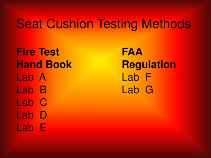
Seat Cushion Testing Methods Fire Test FAA Hand Book Regulation Lab A Lab F Lab B Lab G Lab C Lab D Lab E. All labs participating are using Park Oil Burner Model D. P. L. .

E N D
Seat Cushion Testing MethodsFire Test FAA Hand Book RegulationLab A Lab FLab B Lab GLab CLab DLab E
All labs participating are using Park Oil Burner Model D. P. L.
Modification to BurnerLab A -Tabs, Anemometer @ Airflow inletLab B - Tabs, Flow MeterLab C - Adjustable Air InletLab D - Tabs, Static DiskLab E - Tabs, AnemometerLab F - Tabs, Fuel Filter & Flow meter Lab G - Static Disk
Method of Rotating BurnerLab A - Mechanical Lab B - MechanicalLab C - Electrical Motor ActuatorLab D - MechanicalLab E - MechanicalLab F - ManualLab G - Electrical Motor Actuator
Method of Placing Temperature Measuring Instruments in FlameManual Mechanical Lab A Lab BLab F Lab C Lab D Lab E Lab G
Fuel Lab A - No. 2 Grade Diesel Fuel OilLab B - ASTM D2 Number 2 Lab C - Jet A FuelLab D - No. 2 Home Heating OilLab E - JP8Lab F - No. 2 DieselLab G - Jet A Fuel
Method for Measuring Fuel FlowLab A - Nozzle & Fuel PressureLab B - Flow MeterLab C - Graduated Cylinder and StopwatchLab D - Collection MethodLab E - Graduated Cylinder Lab F - Flow MeterLab G - Timed Collection Method
Intermittent Replacement of NozzleLab A - YesLab B - No Lab C - YesLab D - NoLab E - Yes, not oftenLab F - YesLab G - Yes
Distance of the stabilizer from end of the draft tubeLab A - 4”Lab B - 4.9” Lab C - 2.72”Lab D - 4”Lab E - 3 13/16”Lab F - 4”Lab G - 3 ½”
Distance of the stabilizer from end of the draft tubeLab A - 10.16cmLab B - 12.5cmLab C - 6.91cmLab D - 10.16cmLab E - 8.10cmLab F - 10.16cmLab G - 8.89cm
NozzleLab A - Monarch 2.0 80 CCLab B - Monarch 2.25 80 AR Lab C - Monarch 2.25 80 ARLab D - Monarch 80 CCLab E - Monarch 80 CCLab F - Hago 80 2.25Lab G - Monarch 2.25 80 R
Orientation of IgnitersLab A - 10:00 & 11:00Lab B - 6:00 Lab C - 10:00Lab D - 6:30Lab E - 10:00 & 7:00 Lab F - 12:00Lab G - 9:00 & 6:00
Dimensions of TabsLab A - 2.5” X .75”Lab B - 1.5” x .5” Lab C & G - N/ALab D - 1” X 1”Lab E - 1/16 thick 1 6/16” X ¾” X ¾” Lab F - 2 thin steel Trapezoid, 2" long, measuring 2.25" at outer end; 1.5" at inner end and 2 rectangles 2" long X 1" wide
Dimensions of TabsLab A - 63.5mm X .19.05mmLab B – 38.1mm x 12.7mm Lab C & G - N/ALab D – 25.4mm X 25.4mmLab E – 1.59mm thick 34.93mm X 19.05mm X 19.05mm Lab F - 2 thin steel Trapezoid, 50.8mm long, measuring 2.25" at outer end; 38.1mm at inner end and 2 rectangles 0.8mm" long X 5.4mm wide
Static DiskLab A - N/ALab B - N/A Lab C - N/ALab D - Located 3.5” (8.89 cm) Behind StabilizerLab E - N/ALab F - N/ALab G - Located directly behind Stabilizer
Heat Flux GaugeLab A - Medtherm - H-201Lab B - Vatell - 1000-1ALab C - Hycal - C-1300-A-15-072-X2 Vatell - 1000-1 / S1K Amplifier Medtherm - 64-15-20KLab D - Vatell - 1000-1ALab E - Vatell -Lab F - Vatell - 1000-1Lab G - Medtherm - 64-20-20
Heat Flux Gauge Date of Last CalibrationLab A - 7/11/2003Lab B - 10/8/2002Lab C - Annually or sooner if necessaryLab D -12/4/2003Lab E - 6 months ago Lab F -12/3/2001Lab G -3/7/2003 Annually or sooner if necessary
In Cool Weather Is Heat Flux Cooled With Warm Water to Avoid Condensation on the Surface During Cold Weather? • Lab A - No Ambient Temp. 70° FLab B - No Lab C - Yes, Maintained @ 68° FLab D - NoLab E - No Lab F - NoLab G - No
ThermocoupleLab A - Type K 1/16" gageLab B - Left Blank Lab C - Type K 1/16" gageLab D - Type K-inc.-G-T4-12.00”Lab E - Type K 1/16" gageLab F - Type K 1/16" gageLab G - Type K 1/16" gage
Thermocouple Flame TimeLab A - 5 HoursLab B - 1-3 minutes per calibration Lab C - Variable - Replaced PeriodicallyLab D - No time keptLab E - 45 Seconds Lab F - Less than 30 HoursLab G - 3 Hours, 22 min.
Fuel Pressure GaugeLab A - 100 PSILab B - Not reportedLab C - 85 PSILab D - 93 PSILab E - 100-105 PSILab F - 85 PSILab G - 85 PSI
Last Calibration of Fuel GaugeLab A - 1/30/2004Lab B - 1/2004Lab C - 1995Lab D - 2 years agoLab E - UnknownLab F - 5/16/2002Lab G - Replaced Annually
Wires Used to Secure Fabric Test SpecimenLab A - 1 on BackLab B - 1 on Back Lab C - None – Binder Clips Lab D - 1 on BackLab E - 1 on BackLab F - 1 on BackLab G - 1 on Back
Wires Used to Secure Leather Test SpecimenLab A - 1 on Back 2 on BottomLab B - 3 on Back & 3 on BottomLab C - No Reply Lab D - 1 on Back 2 on BottomLab E - Not reportedLab F - 2 on BackLab G - 3 on Back & 3 on Bottom
Is Chair Frame Affixed to Scale?Lab A - YesLab B - Yes Lab C - Yes Lab D - YesLab E - YesLab F - NoLab G - Yes
Method of Weighing PosttestLab A - Continuous Reader Manual CalculateLab B - Continuous Reader Manual Calculate Lab C - Continuous Reader Manual CalculateLab D - Continuous Reader Manual Calculate Lab E - Continuous Reader Manual Calculate Lab F - Remove Cushions and place on scaleLab G - Computer displays & calculates wt./% wt. Loss continuously
Air Velocity TransducerLab A - Extech Ins. Model 44104 Date Cal. 1/12/2004Lab B - Omega Model HH30A Date Cal. 1/20/2003Lab C - Kurz Model 441S Date Cal. 1/27/2004Lab D - Dwyer Ins. Model 641-6 Date Cal 11/20/2003Lab E - Omega Model HH30A Date Cal. NewLab F - Airflow Ins. Model TA400 Date Cal. 6/5/2002Lab G - Omega Model HHF618 Date Cal. 12/9/2003
Variance in Pre-post Test CalibrationLab A - NoLab B - No Lab C - Seldom Lab D - NoLab E - Generally post test is close to per-testLab F - Not ObservedLab G - Yes, Heat Flux is cooler & Thermocouples are warmer still in spec
Dimensions of Burn ChamberLab A - 10’ X 9’ X 8’Lab B - 18’ x 11.5’ x 13.1’ Lab C - 25’ X 13’ X 14’Lab D - 16’ X 13’ X 14’Lab E - Left BlankLab F - 12’ X 10’ X 8’Lab G - 12’ X 12’ X 8’ –10’ Shed roof
Dimensions of Burn ChamberLab A - 3.m X 2.74m X 2.44mLab B - 5.5m x 3.5m x 4m Lab C - 7.62m X 4m X 4.27mLab D - 4.88m X 4m X 4.27mLab E - Left BlankLab F - 3.66m X 3.m X 2.44mLab G - 3.66m X 3.66m X 2.44m –3.m Shed roof
How Is Air Replenished to Burn ChamberLab A - High Temperature VentilatorLab B - Left Blank Lab C - Rooftop Plenum for minimal cell VentilationLab D - Outside air through wall ventsLab E - No forced air into room Lab F - 7’ X 3’ door with access holes in walls for instrumentationLab G - Adjustable vents every two foot at base & top of walls
Is the Anemometer Permanently Installed?Lab A - Yes Calibration Date 1/12/2004Lab B - No Calibration Date 1/20/2003Lab C - No Calibration Date 1/27/2004Lab D - Yes Calibration Date 8/20/2003Lab E - Yes Calibration Date NewLab F & G - FAR Test Method N/A
ScalesLab A - Weighmaster Model 1300Lab B - Busch 332 Lab C - Toledo Scale 2095Lab D - Rice Lake 1040Lab E - Not ReportedLab F - Penn Scale Model 17300Lab G - Advanced Weight Tech. BM 2424- 100 & IQ+510-2A
Scale CalibrationLab A - 7/7/2003Lab B - 3/16/2003 Lab C - 1/30/2004Lab D - 1/9/2004Lab E - Has Not Been Calibrated by Mfg.Lab F - 6/2/2002Lab G - 5/6/2003