Download
1 / 25
250 likes | 525 Views
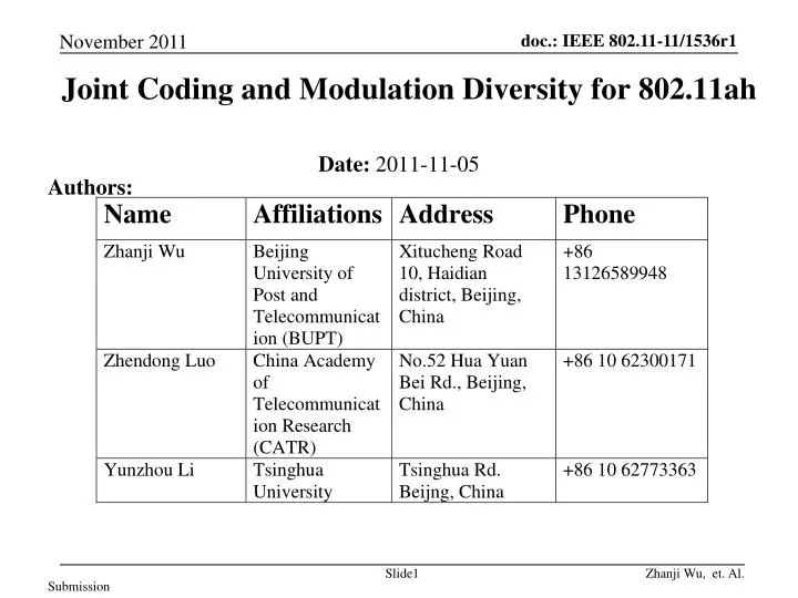
Joint Coding and Modulation Diversity for 802.11ah. Authors:. Date: 2011-11-05. Background. 802.11 ah shall include support for 1 MHz, 2 MHz, 4 MHz, 8 MHz, and 16 MHz PHY transmissions. [1 ] An 802.11ah STA shall support reception of 1 MHz and 2 MHz PHY transmissions. [1 ]

E N D
Joint Coding and Modulation Diversity for 802.11ah Authors: Date: 2011-11-05
Background 802.11ah shall include support for 1 MHz, 2 MHz, 4 MHz, 8 MHz, and 16 MHz PHY transmissions. [1] An 802.11ah STA shall support reception of 1 MHz and 2 MHz PHY transmissions. [1] The 2 MHz PHY transmission shall be an OFDM based waveform consisting of a total of 64 tones (including tones allocated as pilot, guard and DC). This implies a tone spacing of 31.25 kHz. The tone spacing for all other bandwidths PHY transmissions shall be same as the tone spacing in the 2 MHz PHY transmission. Compared with 802.11ac, Tgah has smaller bandwidth and tone spacing .
802.11ah Channel Model • Based on IEEE 802.11-11/0883r1[2] • TGah outdoor channel model 3GPP/3GPP2 SCM (spatial channel model) shall be used to evaluate 11ah outdoor MIMO link and system performance. • TGah indoor channel model The proposed indoor channel model for TGah is based on the 802.11n channel models, which have been widely used in the 802.11 Standard development.
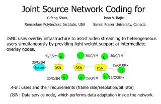
Abstract • Doc.IEEE802.11-11/0069r0[3] proposed to use TGac features as a basis for Tgah. • Doc. IEEE 802.11-10/0336r0 [4] has demonstrated the performance advantages of Joint Coding and Modulation Diversity technique in 802.11 ac system. • Based on our recent research, Joint Coding and Modulation Diversity technique can also improve the overall performance of 802.11ah system, especially in MIMO-OFDM scenario. Therefore, we recommend to introduce this technique to 802.11ah system.
Proposed Transmitter/Receiver Block Diagram NOTES — Red blocks are our proposed amendment. —The number of transmit chains can be not equal to the number of space-time streams — SVD-precoding, codebook-percoding and non-precoding are all supported.
In the amendment, we use rotational modulation method to combine with time diversity of channel coding, spatial diversity of MIMO and frequency diversity of OFDM, which is named joint coding and modulation diversity (JCMD) . As compared with JCMD, the processing scheme in IEEE 802.11n/ac Standard is named bit interleaved coded modulation (BICM) for simplicity. Amendment and simulation are based on the document IEEE 802.11n-2009 ,IEEE 802.11-09/0992r18 and Draft 802.11ac D1.1.
Basic principle of the rotational modulation • According to rotational matrix,rotate the conventional modulated symbol. • The relationship between conventional modulated complex symbol A + j*B and the rotational modulated complex symbol X + j*Y is shown in equation: • where A and B are the I (in-phase) and Q (quadrature) component of the normal QAM, respectively; X and Y are the I and Q component of rotated QAM, respectively
An example of rotated QPSK It is already used in IEEE 802.11ad.
Basic principle of the Spatial Interleaving • In this process , denotes rotated symbol on the stream at time sample. So the interleaving is usual spiral layer interleaving process among all streams at the same time. The method is as follow: • Where is the number of spatial streams. • For example, consider the case, =4: • Corresponding, uses the inverse algorithm at the receiver as follow:
Basic principle of the Spatial Q-Interleaving • In the spatial Q-interleaving process, I components of the complex signals are unchanged, while Q components of signals are changed as follows: • That is to say, Q component on stream i will be moved to the stream (Nss-i-1). • So, it is just a simple reverse interleaver, and the interleaver length is the number of the spatial streams.
Basic principle of the Frequency domainQ-interleaveing • In the frequency domain Q-interleaving process, the I components of the complex signals are unchanged, while Q components of signals are changed as follows: • is the number of subcarriers for data. • That is to say, Q component on subcarrier i will be moved to the subcarrier • . • So, it is just a simple cyclic-shift interleaver, and the linterleaver length is the number of data subcarriers .
Basic principle of demodulation • Due to spatial Q-interleaving and frequency Q-interleaving, fading coefficient of I component is usually different from that of Q component .
Basic principle of demodulation • For example, consider the R-QPSK(rotational quadrature phase-shift keying): • The procedure for demodulation is shown as follows: • Compute the distance between the received point and each reference constellation point. The relationship between the reference constellation point and the rotational constellation point is shown as follows: so
Basic principle of demodulation • 2) Compute the Likelihood ratio (LLR) for every bit. The LLR is the input of the decoder. • For the first bit : • For the second bit: • There is also a simplified algorithm to compute the LLRs: • Similarly, for M-ary QAM(Quadrature amplitude modulation), we should compute LLRs for bits.
Hardware Platform • The platform • Rohde&Schwarz AMU (fading simulator) • 2*FSV(signal analyzer) • 2*SMBV(vector signal generator) • 2*PicoChip PC203 Baseband Unit • 2*RRU
Hardware Simulation Results • SISO: JCMD obtains 2 dB SNR gain at FER=0.1 as compared with BICM.
Hardware Simulation Results 2*2 MIMO: JCMD obtains 3.3dB SNR gain at FER=0.1 as compared with BICM.
Conclusions • It is proved that the proposed scheme has the obvious SNR gains over the current scheme, which implies • Larger coverage area • Lower transmit power • The proposed scheme is easy to be implemented • Rotated QAM modulation • Q-components Interleaver within one OFDM symbol • In a word, the proposed scheme is very suitable for TGah to meet the requirement of PAR.
References [1] 11-11-1294-00-00ah-spec-framework-text-of-11ah-bw-modes.pptx [2] 11-11-0883-01-00ah-Channel-Model-Text.docx [3]3GPP TR 25.996 - Technical Specification Group Radio Access Network; Spatial channel model for Multiple Input Multiple Output (MIMO) simulations [4] 11-11-0069-01-00ah-tgah-Introductory-proposal.ppt [5] 11-11-0336-00-00ac-joint-coding-and-modulation-diversity-to-802-11ac.ppt [6]11-11-1137-02-00ah-specification-framework-for-tgah.docx
Strawpoll • Do you accept JCMD as an enhanced coded modulation scheme to be considered for 802.11ah? -Yes -No -Abstain