Download
1 / 25
420 likes | 868 Views
12V/5A AC Adapter Demoboard L6565 – Quasi-Resonant Controller Demoboard Performance. L6565 – Features Overview. L6565 – Block Diagram. Input of the comparator, the outcoming signal depending on the comp and the VFF pin.

E N D
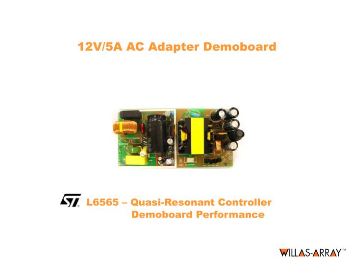
12V/5A AC Adapter DemoboardL6565 – Quasi-Resonant Controller Demoboard Performance
L6565 – Block Diagram Input of the comparator, the outcoming signal depending on the comp and the VFF pin Current sense input, signal exceeds 2V will make the controller running into hiccup mode. Error Amplifier feedback input, FB regulate at 2.5V Output Drive Capability 400mApk UVLO, Vcc turn-on 13.5V and turn-off 9.5V Output of the current comparator block, It will be active when the current signal exceeds 2V Zero Current Detection Once detect the negative going edge demag signal, it triggers the MOSFET turn-on.
L6565 – Internal Supply Block Once the Vcc reaches the startup voltage, the controller begins to operate
L6565 – Zero Current Detection Once the demag pin goes down below 1.6V, the EXT MOSFET will be switched on.To ensure high noise immunity, the triggering block must be armed first: prior to falling below 1.6V, the voltage on pin 5 must experience a positive-going edge exceeding 2.1 V.
Major Parasitic Elements in Flyback Converter where Cd is the total capacitance of the drain node Llk is the leakage inductance of the transformer Lm is the magnetizing inductance of the transformer
VDS Waveform where The first valley occurs at T = Tv, where Tv will be as the following For zero voltage condition, it implies that
QR Timing and Power Relationship MOSFET ON time: MOSFET OFF time: Switching Frequency: Input Power: The switching frequency related to input power: where
Switching Frequency vs. Operating Condition In order to deliver the full loading power at minimum input voltage, the inductance should not exceed the following value:
Switching Frequency Foldback The Tblank function is the function of the Vcomp output
L6565 – Syn-Rect Demoboard Circuit QR mode is the perfect topology for syn-rect because secondary current flow stops before primary MOSFET switches on!
Low Startup Circuit This part is for startup purpose use. The power loss dissipation is much reduced compared with the traditional lossy R-C startup circuit. The charge current pump into the Vcc capacitor at a rate of .
Isolation Gate Drive Transformer L202 – isolated gate drive transformer The gate drive voltage is converted from the secondary current. When the secondary current is large enough, it turns on the Q203, then an output voltage is directly going into the totem pole input and drive the secondary MOSFET. When the secondary current drops to zero, there will be no driving voltage from the isolated gate drive transformer, and Q203 turn-off and the MOSFET will not turn on. Secondary current Isolated gate drive transformer Make use of syn-rect approach, efficiency improves significantly!
Operating Waveforms Primary current Primary current Vdrain Vdrain Vin = 240Vac, Vo=12.3V and Io=5A Vin = 100Vac, Vo=12.3V and Io=5A
Operating Waveforms Primary current Primary current Vdrain Vdrain Vin = 100Vac, Vo=12.3V and Io=5A Vin = 240Vac, Output Short Circuit
Transformer Design (II) In Quasi-Resonant mode control, the current always starting from zero of every switching cycle.
Syn-Rect Demoboard Transformer Np: 520uH