Download
1 / 19
220 likes | 469 Views
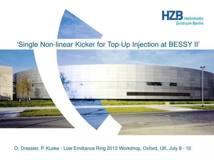
‘Single Non-linear Kicker for Top-Up Injection at BESSY II’. O. Dressler, P. Kuske - L ow Emittance Ring 2013 Workshop, Oxford, UK, July 8 - 10. Content. Non-conventional Injection vs. 4 Kicker Bump Undisturbed Injection in Top-Up-Mode Commissioning of Non-linear Kicker System for BESSY II

E N D
‘Single Non-linear Kicker for Top-Up Injection at BESSY II’ O. Dressler, P. Kuske - Low Emittance Ring 2013 Workshop, Oxford, UK, July 8 - 10
Content • Non-conventional Injection vs. 4 Kicker Bump • Undisturbed Injection in Top-Up-Mode • Commissioning of Non-linear Kicker System for BESSY II • Multipole Injection Kickers for New Storage Rings- Limitations in Modern Accelerators- Technological Challenges- Technical details • Summary and Outlook 2
Non-conventional Injection vs. 4 Kicker Bump Conventional layoutof BESSY II Storage Ring Injection Two similar injection septa and four injection kickers in one (long) straight section, were two kicker magnets are powered in series by one pulse power supply respectively. Non-conventional injection with one single non-linear kicker Application of the two injection septa and one single pulsed non-linear kicker magnet outside the injection straight for special injection procedure in top-up-mode *. Oscillation from injection point to non-linear kicker *Phys. Rev. ST Accel. Beams 10, 123501, ‘New injection scheme using a pulsed quadrupole magnet in electron storage rings’, K. Harada, Y. Kobayashi, T. Miyajima, S. Nagahashi, Photon Factory, 2007. 3
Undisturbed Injection in Top-Up-Mode Aims:‘Top-Up’ operation mode for the BESSY II storage ring, for constant beam current of 300mA, with injection shots every 30s, high accumulation efficiency, without excitations of stored beam. Magnetic field distributions: Dipole Quadrupole Sextupole Octupole Non-linear ‘Non-linear’ refers to the characteristic distribution of induction in the magnet. Advantages: Wide zero field region on axis, reliable zero crossing, flat By-max at certain distance. Tasks for single non-linear kicker magnet system development: Beam optics calculations, magnet system concept, magnetic field calculations, rf power loss estimations, mechanical design, power electronics, control electronics, system integration, etc. 4
Conventional vs. Non-linear Kicker Injection Local Orbit Bump Injection Neighboring kicker magnets (K1 + K2 and K3 + K4) are powered in pairs to form a local pulsed orbit bump for beam accumulation. Non-linear Kicker Magnet Injection One pulsed non-linear kicker magnet located outside the injection straight at an effective phase advance of 45° in reference to the injection point. Turn-by-turn measurement of horizontal and vertical beam oscillations due to kicker schemes. • 4-kicker injection bump optimized for small excitation. • Injection efficiency ~ 80% • rms orbit perturbationhorizontal ~ 1.000mm vertical ~ 0.500mm • Standard injection, beam current 300mA • Perturbation of the stored beam in both planes • Single non-linear kicker injection, not completely optimized. • Injection efficiency ~ 80% • rms orbit perturbationhorizontal ~ 0.060mm vertical ~ 0.015mm • Injection up to a beam current of 300mA possible
Commissioning of Non-linear Kicker magnet (1) Methodology of Measurements:The kicker magnet was excited by its nominal current (4 x 700A). The kicker timing relative to the storage ring injection was changed stepwise [µs]. The kick strength [kick/µrad] into either horizontal or vertical direction, measured at a particular horizontal / vertical geometric position (x / y [mm]) of the beam in the vacuum pipe, is shown in the plots. Set-up:All 4 magnet coils were powered in parallel, on 2 transducers for upper and lower magnet half respectively. Maximal efforts for tuning of current symmetry were done.
Commissioning of Non-linear Kicker magnet (2) Set-up:The 2 magnet coils magnet coils of top and bottom magnet half were connected in series, on 2 transducers for upper and lower magnet half respectively, and tuned for best current, and hence, magnetic field symmetry. Result: • In both coil set-ups a minimum of beam excitation in horizontal direction can be detected. • While in the first case as minimum for vertical beam perturbations is far away from the horizontal minimum, in the second case one finds much better agreement with the theory. • Assumption that only a series connection of all four kicker coils will achieve horizontal and vertical minima at the same x / y position.
Non-linear Kicker Magnet, 2D B-Field Calculations Evolution of Design: 4 conductors, 4 coils, with ceramics support and vacuum pipe profile. Desired: 4 currents into one direction The kicker magnet posses mirror symmetry on its horizontal and vertical middle axis. Direction of scalability of design. Vertical aperture required for storage ring is most limiting factor. Specifications: Bymax. ≥ 20 mT, depiction in [G], (1 G = 1•10-4 T) Bymax. at y = 0 and x = +10 mm Bymin. at y = 0 and x = -10 mm (symmetry condition) Bx = 0 along y = 0 Measures in [cm] Final design with bore of vacuum pipe and titanized ceramics support. POISSON SUPERFISH, Report No. LA-UR-96-1834, 7 Feb. 2007, Los Alamos National Laboratory
Magnetic Field Measurement vs. ANSYS Calculation Problem: Reliable and precise B-field measurements in small bores. 9
Multipole Kicker Magnets - Limitations by Accelerator Multipole Injection Kicker (MIK) development at SOLEIL for MAX VI is succeeding BESSY NL-Kicker design. Advantages of MIK Concept: • Non-disturbed stored beam in top-up injection mode. • Octupole like field distribution with zero field on axis and flat By-field maximum at a certain distance. Only injected beam deflected. Limitations of MIK Concept: • Positioning of the MIK within the storage ring by considering non-linear optics of modern accelerators. Changes in optics may require to move kicker. • Vertical aperture requirements limit positioning of the kicker coils; injected beam at chosen position may not be at By-field maximum of non-linear field distribution. • Limitation for the excitation pulse length by revolution time; injected beam only kicked once. • Small emittance of injected beam required. Reference: S.C. Leemann, Phys. Rev. ST Accel. Beams 15, 050705, ‘Pulsed sextupole injection for Sweden’s new light source’ MAX IV, 2012. 10
Multipole Kicker Magnets - Technological Challenges Technological Challenges of MIK Concept: • Precise wire positioning in alumina (1/100 mm). • Sensitive vacuum system with welded flanges to ceramics. • Uniform coating of alumina with Titanium for mirror current path and good rf containment. • Low inductance pulse power circuit for required high pulse currents at short pulse duration. Technical details: • Eddy currents in neighboring metallic surfaces cause field distortion, asymmetries and weakening. • Proper contacting of coated surface to avoid rf power loss and temperature rise of component. • Pulsed PS outside the tunnel foreseen, to avoid risk of radiation damageon switching power electronics. • Now long cables are necessary with ‘pseudo matching’ to keep load impedance low. Reference: P. Lebasque, Magnetic and electric evaluation in transient mode of the Bessy-II MIK design … (collaboration report), March 2013. 11
Comparison of Different Pulse Circuit Topologies Traveling Wave Circuit Characteristic impedances: 50, 25, 12.5Ω Con: • Impedance matching required. • Small impedance mismatch by load inductance deteriorates slew rate of pulse current. • High charging voltage necessary because of system impedance. Pro: • Pulser unit in save distance to magnet, therefore no radiation.exposure of power electronics • Small attenuation by cable only. Lumped Element Circuit Pro: • High currents on small load impedance. • High accuracy possible. • Low ripple on pulse top. Con: • Small distance to magnet. • Foot width vs. pulse top of half-sine pulse current.
Schematics of Linear Transducer Schematics of Linear Transducer Concept: Pulser / Transducer / Magnet Transformation ratio 1:1, only prim. + sec. stray inductance add on (1) Transducer in saturation M - Mutual inductance, K - coupling ratio Scope picture as example for non-linearity and saturation of core material (2) (3) CT2 (4) (3) in (2) CT1 LE - Apparent inductance of pulser circuit, in (4) (5) Properties: • Primary and secondary stray inductance of windings and connections • Non-complete coupling • Eddy current and hysteresis losses in core material, possible saturation • Transformation ratio ≠ 1:1 causes transformation (increase) of load impedances and hence longer current pulses β in (5) (6) α in (6) (7) * Heinz Knoepfel, S. 143, Physical effects and generation methods concerning pulsed fields up to the megaoersted level, Verlag: North-Holland Publ. Co. (1970), ISBN-10: 0-444-10035-0
MLS- and Diagnostic Kicker System Slotted pipe kicker in MLS SR with solid state pulser attached Thyratron pulser system for diagnostic kicker in BESSY SR ÎP = 4000 A half sine τ= 1.5µs fr up to 10 Hz ÎP = 800 A half sine τ= 2.3µs fr up to 10 Hz Amplitude stability 0.1 % References: • F. Marhauser, O. Dressler, V. Dürr, J. Feikes, ‘Impedances in Slotted-Pipe Kicker Magnets’, proceedings of the EPAC, Edinburgh, Scotland, 2006. • O. Dressler, J. Feikes, ‘Diagnostic Kicker System as a Versatile Tool for Storage Ring Characterizations’, proceedings of the EPAC, Edinburgh, Scotland, 2006. • O. Dressler, V. Pickert, C. Rediess, ‘IGBT Driver Circuit in Inductive Adder Technology for Pulsed Power Applications’, proceedings of the PCIM, Nürnberg, 2008.
Realization of Magnet and Connections 2D Magnet Model Schematics of Electrical Connections Four Kicker Coils Symmetry axis Sectional View 3D Magnet Model Options for Coil Interconnections • 2 coils in parallel on 1 transducer (top/bottom), 2 circuits in parallel. • 2 top and 2 bottom coils in series using 1 transducer respectively (installed). • 4 coils in series on 1 transducer (will be installed this August).
Acknowledgement We would like to acknowledge the efforts of the HZB project team:P. Kuske, M. Dirsat, T. Atkinson and O. Dressler, H. Rast (TU Dortmund). We also appreciate the prosperous collaboration of MAX VI and SOLEIL. Especially to mention is the MIK development team of P. Lebasque at SOLEIL.
Summary • Tests of NL-kicker in BESSY II storage ring for beam injection was successful. • RF power loss was reduced by complete coating of surfaces with titanium. • B-field amplitude stability is no issue since only one pulse power supply is used. Injected beam needs to stay within dynamic aperture boundaries. • Studies of beam excitation and injection efficiency show promising results. Further studies in top-up mode are ongoing. • The series connection of all coils to reduce imbalance further is coming this summer.
Outlook • Development efforts by a collaboration of SOLEIL and Max VI to deploy MIK concept for injection into modern accelerators. • Higher integration of magnet functionality, e.g. the ceramics chamber is becoming part of the magnet vacuum system to relax pulser requirements, and also facilitate air-cooling. • Advance from a ‘prove of principle’ component and test system to a highly reliable injection kicker system for 24/7 operation. • Development of a dedicated pulse power supply having smallest circuit inductance, based on solid state technology and outside the storage ring.