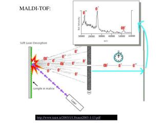
Download
1 / 21
210 likes | 386 Views
ALICE TOF. DCS Workshop 6-7 October 2005 O. Pinazza and F. Cindolo for the TOF group. TOF DCS status report. TOF HV subsystem TOF LV subsystem FEE control planning FSM and integration Plans Answers: TOF inventory TOF overview drawing. TOF HV hardware. TOF HV controls.

E N D
ALICE TOF DCS Workshop 6-7 October 2005 O. Pinazza and F. Cindolo for the TOF group
TOF DCS status report • TOF HV subsystem • TOF LV subsystem • FEE control planning • FSM and integration • Plans • Answers: • TOF inventory • TOF overview drawing
TOF HV controls • standard: PVSS + framework + OPC • just an alternative data archive (fprintf) and customized user panels
TOF HV status • the system is on since 2003 with some improvements • at present a test for cosmics is running at CERN and the monitor and control system are working well • the system is very light: 12 channels • but is running for months on a low performance laptop in the public Cern network
TOF LV: the CAEN ALICE-box • CAEN custom device, derived from an EASY crate
TOF LV: Alice-box • TOF has tested the thermal performance of the water cooled case in magnetic field simulating a full load
TOF LV: Alice-box • TOF has tested the LV connections and controls in the “almost” final position at Point2
TOF LV controls • at the moment the Framework does not include datapoints for the TOF crate, but JCOP is working on it • TOF has programmed its crate and channels in PVSS • the panels are plain and not yet optimized
TOF FEE • the Front-End components are being delivered in this period and will be tested in our lab • the controls will be programmed after the tests; we will use a linux PC (with the PCI board for the VME crate) with a DIM server and another PC with the PVSS project
TOF FSM and the integration TOF is made of 18 azimouthal sectors (supermodules) HV partition = 1 module one sector is made of 5 modules LV partition = 1 quarter of a sector one sector is made of 4 quarters
TOF FSM TOFinternal ECS requirement
TOF DCS plans • revision of the LV subsystem using Framework • begin the FEE subsystem with DIM • continue the FSM schema in strict agreement with ECS • test the ROOT-PVSS interface (?)
TOF Readout Scheme Thr - Trigger TOF Module Clock L1 - L2 - Clock Signals L1 - L2 Busy F E C FEA FEA L0 - T0 Signals L0 - T0 To EB FE Data FE Data LTU LTM- (CLD) ALICE BOX D-RORC Busy DDL L1 - L2a - L2r TRM TRM Readout Data - VME DRM Clock PCSC FE Data FE Data SCL UX CR FEA FEA F E C TOF Module 45 m 90 m Thr – Trigger • The ALICE TOF ReadOut and Data Acquisition (TARODA) consist of : • TRDS (TOF Readout System) located on the detector • TDCS (TOF Detector Control System) • TDQM (TOF Detector Quality Monitor) • TECS (TOF Run Control System) Equipment Computer Eth SCL
TOF [FSM] Database(s) Oracle 10g 1 18 180 4 72 4 16 2 72 74 72 180 1 900 900 07/10/05 PVSS II PVSS II PVSS II Control room (ACR) OPCclient DIMclient User interface B. Overview Drawings Ethernet CR3 CR3 CR3 CR3 CR3 CR3 PVSS II PVSS II PVSS II PVSS II PVSS II PVSS II DIMclient OPC client OPC client OPC client E Wiener OPCserver DIP Modbus/TCP CR3 CAEN OPCserver CAEN OPCserver [FED] DIMserver PCI-CAN PCDCS PCI E E E E C SG2 E- OL GasPVSS SCL [GWG] PLC TS/CVSCADA CR4-Z02/03 SG2 SY1527 C Gas UX-A,B UX-A,B UX-A,B 48 V PS Maciste Eth Switch UX-C SY1527 PLC HV CR5 LVCan Gas VME(Trigger) CoolingPlant CLK HV ALICE Box distribution DC-DC LV Can Detector Detector TRMs DRM LTM CLD (readout crates) Detector Detector DDL High Voltage Low Voltage FEE Crate Control Detector Cooling Gas system
Slow Control and FERO • HV – LV, gas and cooling monitor : Links Frequency • HV 90*2 V-I OPC - CAEN SY2527 30 s • Cooling 16 PLC 20 s • Alarms (SEE) 72 16 bits DIM Variable • Gas PLC Variable • Interlocks (Hard/Soft) 6 PLC Fast/10 s • Temperature readout : • FE Sensors - 72 x 8 SCL (DIM) 30 s • LV Sensors - 4 x 18 SCL (DIM) 30 s • Cooling - 4 x 18 PLC 30 s • Physical links : • Links Status - 4 x 18 SCL 30 s • Readout FERO configuration parameters (archived on DB): • PDL 42*72 8 bits SCL (DIM) Setup • VTh 16*72 10 bits SCL (DIM) Setup • TRM 10*72 8 bits SCL (DIM) Setup • DRM 72 8 bits SCL (DIM) Setup • PAD on 2400*72 1 bit SCL(DIM) Setup • HPTDC on 300*72 8 bits SCL (DIM) Setup • ToT offeset 300*72 8 bits SCL(DIM) Setup
FERO Processes on PCDCS SCL link on DRM DDL controls on DRM Set THR, Matrix, Trigger Masks and Hardware Registers LV and HV Power management Monitoring distribution system FED Error check : Data transfer Electronic SEE Temperature, Pressureand Humidity DCS and FERO Control Operations PVSS TRM FEA Private VME Private SCL OPC RTC RTC PCDCS DRM LV CAN H V TOF DCS Private GAS PLC PLC User Control COOL ING Private PLC