Download
1 / 9
90 likes | 287 Views
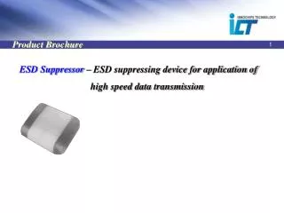
Physical Circuit-Device Simulation of ESD and Power Devices. V. Axelrad, H. Hayashi*, I. Kurachi** SEQUOIA Design Systems, USA *OKI Semiconductor, Japan **Current address Powerchip Technology Corporation, Taiwan. +. Background. Conventional ESD protection design technique.

E N D
Physical Circuit-Device Simulation of ESD and Power Devices V. Axelrad, H. Hayashi*, I. Kurachi** SEQUOIA Design Systems, USA *OKI Semiconductor, Japan **Current address Powerchip Technology Corporation, Taiwan
+ Background Conventional ESD protection design technique ESD Protection device VDD The optimization of the ESD protection device itself with higher capability of ESD protection Internal Circuit VOUT GND Problems: ■ESD Protection device can not be large by area penalty. ■ESD tolerance of high voltage devices is low in comparison with logic device, because breakdown current is not uniform in p-n junctions. ■ESD protection design is difficult in optimization of protection device only. Requirement Optimization of the ESD protection network
Proposed ESD Protection Design Technique Trial Experiment Circuit Design Vth, Ids, BVsd Optimization Calibration W Gate R Protection Source Drain Mixed-Mode Simulation Reflect TEG The ESD parameters by the TLP measurement Layout Design W Current Li Ron Nw Calibration Ln Lp Vt1 Vhold ESD Input Pulse Voltage
Simulation Technique 2D based-ESD Mixed-Mode Simulator in Sequoia Design Systems Inc. • Features of Sequoia tools: • 2D FEM models for quick calibration and fast calculation • Auto mesh and electrode generation using GUI • Interface connected to structure of process simulation with TIF format • Good convergence under high current level
Calibration to TLP Measurement TLP measurements and calibrated simulation results for a high-voltage NMOSFET. Higher triggering voltage and more complex behavior. TLP resolution limits measured current accuracy at low levels < 1e-3A. TLP measurements and calibrated simulation results for a 0.13um ESD protection NMOSFET. BTBT tunneling leakage is clearly seen as a straight line in the pre-breakdown part of the curve.
Example of ESD Protection Circuit using ggNMOS M2 M1 A total of 7 FEM devices is included: 3xNMOS, 2xPMOS, 2xDiodes.
Result: Physical Analysis Self-Heating and Current during HBM event Self-heating Current IO pad potential waveforms for HBM 2kV, CDM 500V and MM 100V stress, the first 10ns of ESD stress response shown in the large picture, 300ns in the insert at lower right. The amount of current and self-heating in each device is key to judgment.
QTAT Development for ESD Protection Design Process and device design Circuit and layout design Prediction of device performance using previous model parameter ESD Target (e.g., HBM>2kV) Trial production ESD test circuit TLP measurement Optimization of circuit network using mixed-mode simulation Model parameter extraction of mixed-mode simulation Layout design Simultaneous development is possible through a mixed-mode parameter.
Conclusions: • We have applied our ESD protection design methodology • with a combined use of a TLP measurement and mixed-mode • simulation to high-voltage devices. • 2. Calibration is easy because of a few physical parameters and • a clear relation between parameters and electrical characteristics. • 3. Using 2D FEM model, simulation times are between 3 minutes (HBM) to • 13 minutes (MM) on quod-core machine. Requirement of the short • period of IO design is satisfied. • 4. Our approach is effective for design of advanced ESD protection • in logic as well as power ICs.