Download
1 / 11
110 likes | 113 Views
Learn how to simulate and modify circuits using a helpful step-by-step guide. Understand node numbering, DC operating point analysis, circuit modification, and transient analysis.

E N D
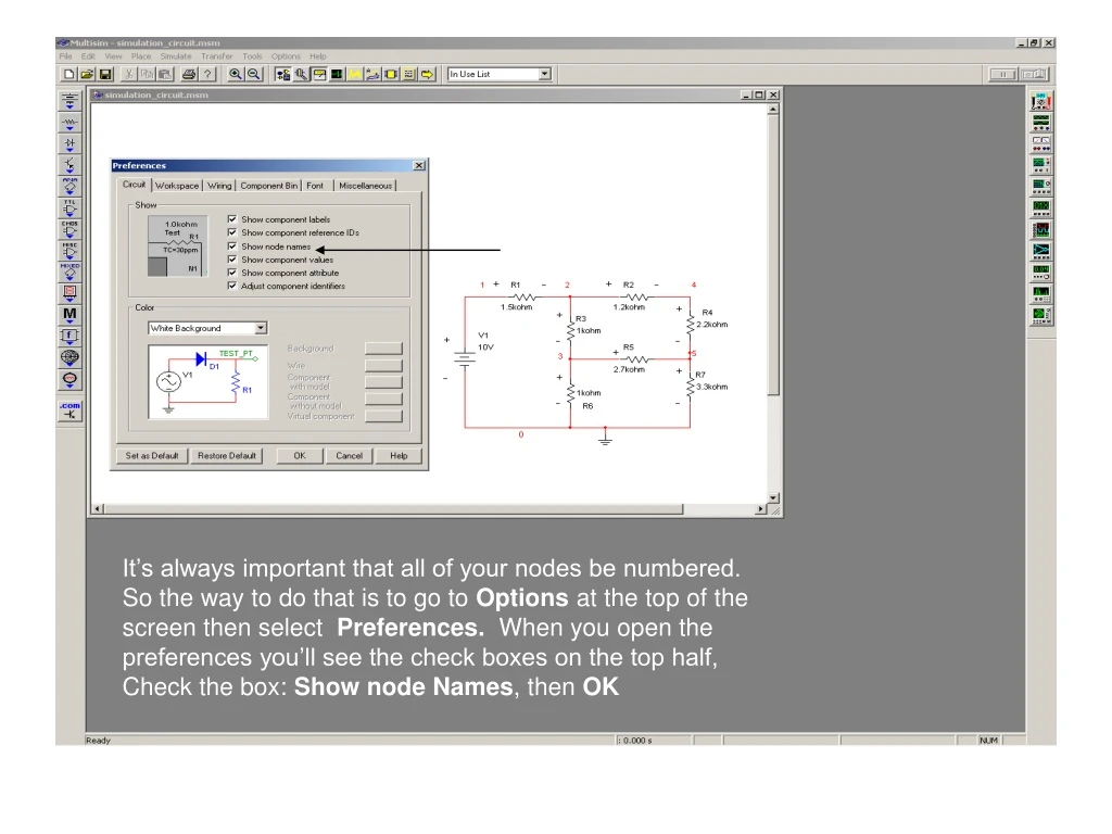
It’s always important that all of your nodes be numbered. So the way to do that is to go to Options at the top of the screen then select Preferences. When you open the preferences you’ll see the check boxes on the top half, Check the box: Show node Names,then OK
DC Operating Point Once you have your circuit you’ll want to simulate it. The way that could be done is to go to the Simulatemenu, Analysis then DC Operating Point. The point of the DC operating point to measure the currents and voltages through out the circuit.
Notice that all the node numbers and current branches are in the left list. You can select which items you want analyzed by selecting it and moving it over to the right side list by highlighting it and pressing the button in the middle marked Plot During Simulation.
You should get a box with readings in it saying at which nodes the voltages are as follows. And something must be understood about the current readings. In this case it’s the reading vv1# branch. That reading is always the current flowing into the positive side of the V1.
Modifying the Circuit B A It’s also important to be able to modify the circuit when you have to. In this case lets change the resistor value. You double click on the resistor and a window will show up. There are four tabs: Label, Display, Value and Fault. The Value tab is the one where you are able to change the resistance level (arrow A). It is also possible to change the tolerance level and even the temperature of the resistor but that won’t be the point of this lab. You can also press Replace next to okay and it will give you the list of preset resistors to replace it with. There is also the box (Arrow B) that allows to change the units from picohms to terraohms.
There is also the label tab, and what that does is allow you to change the Resistor number or what you want to be shown or if you want you could add in an extra label to it. The graph below is to be able to write the label and value in a more organized way on the schematic but isn’t necessary. The Fault tab is meant to set faults within the component, such as short circuits, open circuits, or leakage. But using this won’t be needed.
Potentiometer Capacitor inductor transformers To add components is simple, just go to the list of components and choose something you would like to include in the circuit. You can make any circuit you want to, but the only thing that you need to know would be how to set it up in terms of output and input terminals and making sure that it flows with the circuit or else you get an error symbol when you try to run a simulation.
Transient Analysis AC power supply To do Transient Analysis, the first thing you need to do is to change your power supply to a AC type power supply. If you were to use a DC type your graph would just be a straight line because transient analysis measures the change of voltage with respect to time and in DC there is no change, it’s a constant voltage.
A B C A window will appear and it will talk about setting the parameters. It’ll already have preset times and numbers and you stick with them to see how it looks after you simulate it. If you do want to change it then you could begin, using the start and stop time (Arrow A). You could make the stop time smaller and that would enlarge the picture you have of the current. You could also change the number of points to make your curve. Right now it’s already preset (Arrow C) for a hundred points or you could increase it or decrease it (Arrow B).
A Now before you can simulate it, you still have to plot the output variables. So click on the Output Variables tab. Highlight the variables that you want simulated and then press the Plot During Simulation button. After it shows up on the other list then you can simulate the circuit.