Download
1 / 39
390 likes | 402 Views
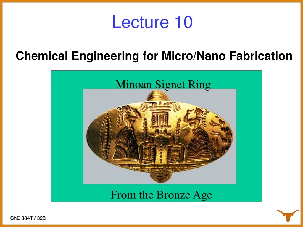
This lecture discusses the Minoan Signet Ring from the Bronze Age and its relevance to chemical engineering for micro/nano fabrication. Topics include birefringent crystals, pattern density effects, step and flash imprint lithography, and residual layer control.

E N D
Minoan Signet Ring From the Bronze Age Lecture 10 Chemical Engineering for Micro/Nano Fabrication
Birefringent Crystals CaF2 CaCO3
Pattern Density Effects Easiest… Easy… Very Difficult! “Residual layer”
Template Template Planarization layer Substrate Template Step and Flash Imprint Lithography Fused silica template, coated with release layer • S-FIL fluid dispenser • Ink jet system Planarization layer Step 1: Dispense drops Substrate Step 2: Lower template and fill pattern • Template filling driven by capillary action • low imprint pressure and room temperature process Step 3: Polymerize S-FIL fluid with UV exposure Planarization layer Substrate Step & Repeat Step 4: Separate template from substrate Planarization layer Substrate
S-FIL vs. Optical Lithography Schematic Greatly simplified and lower cost process Imprint Lithography Standard Optical Lithography
First Publication of SFIL Colburn, et.al “Step and Flash Imprint Lithography: A New Approach to High-Resolution Patterning,” Proc. SPIE3676 379-389 (1999) Matt Colburn, et. al 40 nm images First SFIL tool
S.V. Sreenivasan Residual Layer “Issues” with SFIL are: • Templates • Orientation control • Making 1X templates • Residual layer control • Defects • Template wear • Alignment • Throughput • Templates • Orientation control • Making 1X templates • Residual layer control • Defects • Template wear • Alignment • Throughput
Self-Leveling Scheme using Template Flexure Template-substrate interface Template Remote center of rotation Flexure Schematic Z head Template calibration stage Template flexure Template chuck B. J. Choi, S. Johnson, M. Colburn, S.V. Sreenivasan, C. G. Willson, “Design of Orientation Stages for Step and Flash Imprint Lithography,” Journal of Int. Societies for Precision Engineering and Nanotechnology, Volume 25, No. 3, pp. 192-199, July, 2001. Template Wafer Wafer Tip/Tilt stage Theta stage XY stage
26 nm metal 1 SFIL Lithography 2nm Replication (Rogers et al, Illinois) 11nm lines and spaces 14 nm posts Line and 100 nm via
Claims of competitors and detractors Obviously, you cannot ……. control residual layer thickness manage defects….no pellicle??? achieve layer to layer alignment achieve workable throughput Abut fields, etc, etc.
Residual Layers Residual Layer Residual Layer Thickness Control Residual Layer is due to the inevitableundisplaced liquid Avoid: Non-uniformities Residual layer needs to be thin and uniform
Focus on Continuous Process Improvement 2. 3. 1. 4. • Minimize mean and standard deviation of residual layer • Key drivers: chuck flatness, inkjet drop volume and location controls, evaporation.
28 nm HP Residual layer thickness fully populated wafer Residual Layer Thickness MeasurementsEarly Results Residual layer mean <20nm and thickness variation to < 6 nm TIR
Residual Layer Control Today • Software and hardware have been developed to correctly jet resist, and control the spreading of the resist.
1) Why do you think 1X projection lithography replaced contact printing in the early 80’s?? Don’t you learn from history??2) Do you propose attempt to do lithography without a pellicle??!! Defects
Template Before and After Imprints Filthy Template Template after second imprint Template prior to imprint All visible defects disappear from the template. Printing is the best way to clean an SFIL template! This is our “Pellicle”
Defect Density Trend Similar to Immersion….early work • Data measured on imprinted wafers – includes all sources of defects • Steady improvement in defect density – • Rate approximately one order of magnitude per year • very similar to immersion lithography learning curve
Defect Control in the current Canon Tool 1 particle / 2500 wafers !
Electrical Testing for Defectivity Serpentine conductor testing
Field-To-Field Alignment • Moiré metrology originally developed for X-Ray litho(Smith, Moon) • Sub-nanometer resolution, inclined optics • Insensitive to film thickness variations • Alignment and scale/shape correction are performed “in-liquid” which is typically a 15nm residual layer 25
Loadcell Pads Gimbal Overlay: Scale/Shape Correction Mechanism SiC Chuck & Template 28
Throughput • Full Wafer printing is not possible now • Here alignment is the issue • Fill time is the rate limiting step • Control of dispense pattern • Resist material design • Engineering the separation step • Minimize defects • Maximize template life time
The Fill StepAdaptive dispense, spread and release in 1.5 sec
Nanofluidics: RLT Control and High Throughput High density Low Density Drop dispense addresses template geometry variation, pattern-specific directionality of flow, multi-scale fluid/solid mechanics, etc. Need to solve inverse problem. √ Med Density 39