Download
1 / 10
100 likes | 236 Views
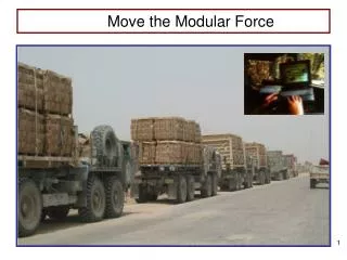
Stress Analyses of Modular Coils and Coil structure Part 1 – EM Analysis. H.M. Fan PPPL April 2, 2002. ANSYS Model for Winding Pack and Tee. Note: Tee and spacer were unselected in the EM analysis. Currents, Materials, and Element Type Numbers.

E N D
Stress Analyses of Modular Coils and Coil structure Part 1 – EM Analysis H.M. Fan PPPL April 2, 2002
ANSYS Model for Winding Pack and Tee Note: Tee and spacer were unselected in the EM analysis
Currents, Materials, and Element Type Numbers •Currents are selected from 2T high beta scenario at 0.0 seconds Coil Part Current Turn Material Elem. Type (A/turn) Number Number M1 Coil 22228 36 1 3 Tee - - 2 3 Spacer - - 3 3 M2 Coil 22998 36 4 2 Tee - - 5 2 Spacer - - 6 2 M3 Coil 17518 36 7 1 Tee - - 8 1 Spacer - - 9 1 PF1 16703 56 10 4 PF2 16703 68 10 5 PF3 5356 112 10 6 PF4 4967 100 10 7 PF5 -5625 24 10 8 PF6 740 8 10 9 TF 2071 12 11 10 Plasma 0 1 11 11
Magnetic Flux Density of PF and TF Coils Flux density unit in Tesla
Magnetic Flux Density of Modular Coils Flux density unit in Tesla
Element Magnetic Forces of PF Coils Magnetic force unit in Newton Magnitude based vector plot Uniform vector plot
Element Magnetic Forces of TF Coils Uniform vector plot Magnitude based vector plot Uniform vector plot Magnetic force unit in Newton
Element Magnetic Forces of Modular Coils Magnetic force unit in Newton Magnitude based vector plot
Structural Shell Model Developed by offsetting “paver” mesh of shell inner surface Equivalencing of outer surface nodes not complete (cracks visible) Need to adjust offset nodes to radial planes and add wings for cyclic sym
Structural Shell Model Spacer E=500-MPa Tee / Shell E=200E3-MPa Cyclic Sym boundary Constraint Eq between tee nodes and shell elems Coil E=0.6(100E3)+0.4(500) E=60.2E3-MPa