Download
1 / 23
230 likes | 407 Views
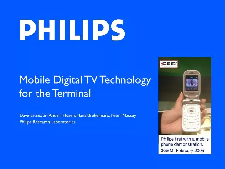
Mobile Digital TV Technology for the Terminal. Dave Evans, Sri Andari Husen, Hans Brekelmans, Peter Massey Philips Research Laboratories. Philips first with a mobile phone demonstration. 3GSM, February 2005. Technology for the Terminal. Technical challenge RF Tuner Antenna

E N D
Mobile Digital TV Technology for the Terminal Dave Evans, Sri Andari Husen, Hans Brekelmans, Peter Massey Philips Research Laboratories Philips first with a mobile phone demonstration. 3GSM, February 2005
Technology for the Terminal • Technical challenge • RF Tuner • Antenna • TV coexistence in the phone • Channel decoding – dealing with Doppler • What next? • Conclusion
Technical Challenge • Reception in all situations • Good picture quality • Limited impact on phone battery life • Global usage • Mobile TV is now addressing the issues that are familiar in the design of mobile terminals • Size • Performance • Reception on the move • Low power • Multi-standard
Cellular transceiver Coexistence TV tuner Channel decoder Media processor TV in the phone – Generalised architecture Additional elements for broadcast TV reception Display Baseband controller + interface + Software Philips supplies complete system solutions for the mobile terminal
RF Tuner • Major challenge was power consumption • Starting point ~500mW • Now >100mW (>5% with DVB-H time slicing) • Low/zero IF design • Minimal off-chip components • 470 to 860 MHz operation • Separate on chip LNA for 1452 to 1675 MHz operation • On-going work to improve performance
Mobile DTV Antenna • Two issues: • Close proximity between mobile DTV and GSM antennas • Common ground plane • Coupling between them disturbs the GSM antenna and affects its performance • Co-design of the GSM and Mobile DTV antennas is essential • Signal coupling from GSM to mobile DTV antenna is high • Need to incorporate GSM signal blocking • Ideally continuous operation from 470 to above 700 MHz • Limited to ~700 MHz to assist GSM coexistence
TV filter must be reflective at GSM Interaction between GSM & DVB-H Strong coupling, poor isolation DVB-H port GSM feed GSM DVB-H Reflection phase matters!
Interaction between GSM & DVB-H open circuit at DVB-H monopole DVB-H port GSM feed short circuit at DVB-H monopole GSM S11 • GSM seriously effected by impedance of DVB-H circuit. Co-design is necessary.
Antenna + RF Tuner • Compact PIFA • 470 to 700 MHz continuous operation • Antenna includes a GSM trap Feed tab Integrated GSM filter Antenna & RF tuner
TV Coexistence in the Phone • Interference from GSM900 transmissions due to very close co-location • DTV receiver blocking • 58 dB isolation between GSM TX and mobile DTV receiver is required • Potential solutions • Isolation between antennas – limited to between 6 to 10 dB • Can be improved by use of GSM trap within mobile DTV antenna, ~20 dB • Managing GSM transmission at the terminal – limited scope • Managing DVB-H transmissions – not possible • Power cancellation – not very promising • Receiver filter, good solution but requires frequency separation – restricts channel usage. TV channel 50 (~700 MHz) OK, extending this to 54/55 desired • Coexistence best achieved by filter before TV RX + antenna with GSM trap • Out-of-band noise – high pass filter at GSM TX output
Broadband matching + filtering, PIFA to LNA NF <4dB, 480 to 720 MHz G >17dB, 470 to 710 MHz 50dB attenuation above 877MHz
Channel Decoding • Key issue for mobile TV • Reception at high vehicle speed • Problem • Impact of Doppler effects on OFDM • Channel changes during symbol period • Inter carrier interference (ICI) • 150 kph equates to typically 100 Hz Doppler • 8k DVB-T mode has 1.1 kHz subcarrier spacing • Solution • Channel estimation and Doppler compensation • ICI cancellation
Mobile multipath channel • The faster the vehicle, the more severe the ICI, the poorer the reception. • Challenge: DVB-T/H 8K mode (fs = 1.12 kHz) reliable high throughput reception under high Doppler frequency (10% fs) with low complexity.
Inter-Carrier Interference Noise Wanted received signal Channel Estimation The received signal in frequency domain is approximated as follows: where: • His the complex channel transfer function vector for all the subcarriers • H’is the the temporal derivative of H (proportional to vehicle speed) • Ξ is the fixed Inter-Carrier Interference spreading matrix • ais the transmitted data vector • nis a complex circular white Gaussian noise vector
empty carriers pilots data carriers time frequency Channel Estimation • Estimation of H: rather than time interpolation, frequency interpolation • Estimation of H’: calculated from H estimation of past and future symbols OFDM symbol
Inter-carrier Interference • ICI level is not constant but varies over frequency • ICI level per sub-carrier can be estimated from H’ • Soft demapper takes into account ICI level per sub-carrier, rather than average ICI power
channel estimation Basic Channel Decoding Scheme Log likelihood ratio per bit Data Estimation Soft demapper To de-interleaver & Viterbi decoder
channel estimation Soft QAM demapper ICI cancellation Overall Scheme To de-interleaver & Viterbi decoder Log likelihood ratio per bit Data Estimation (Using regenerated ICI)
Final points on channel decoding • Channel model • MBRAI specification defines the use of COST 207 TU6 profile • Modeling of the Doppler spectrum is not defined • System performance is very sensitive to model parameters • No conformance tests are defined in for the complete channel model • Caution needs when comparing performance
What next? • On-going work to improve performance • Further reductions in power consumption • Move to a CMOS architecture • Single chip solution that includes channel decoder • Emerging RF filter technologies including MEMS • Antenna diversity, extra dBs are very useful – gain of a few dBs? • Technology will evolve to meet that in the terminal, convergence! • Multi-standard solutions • Needed now to support multi-standard multi-band cellular requirements • Also required for WLAN/BT, mobile DTV and GPS • Reconfigurable, highly digitised radios • Coexistence in the phone • Exploitation of multiple radios to assist mobile DTV reception - diversity
Conclusion • Keys issues and challenges are understood • Solutions are available now • On-going process of performance improvement • Continuing to maintain the leading position of Philips Complete systems solution shown at IFA, Berlin, September 2005