Download
1 / 9
90 likes | 264 Views
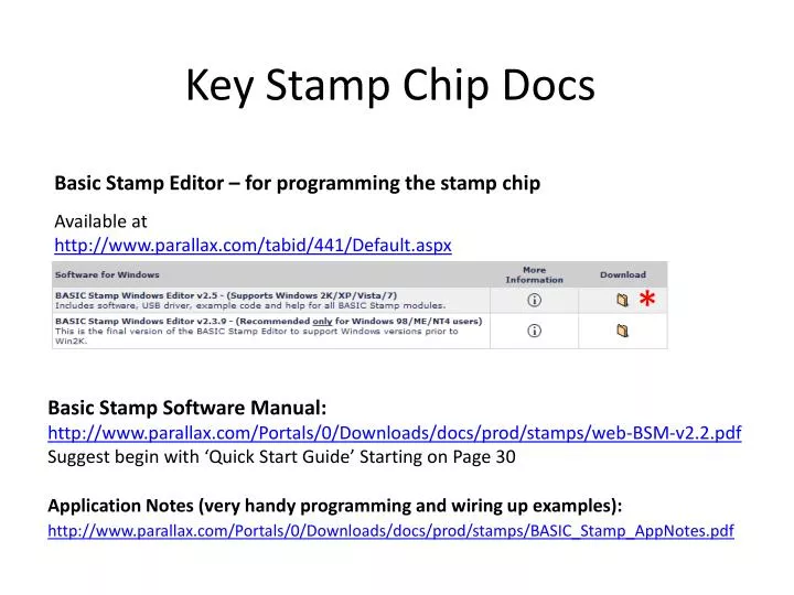
Basic Stamp Editor – for programming the stamp chip. Key Stamp Chip Docs. Available at http://www.parallax.com/tabid/441/Default.aspx. *. Basic Stamp Software Manual: http://www.parallax.com/Portals/0/Downloads/docs/prod/stamps/web-BSM-v2.2.pdf

E N D
Basic Stamp Editor – for programming the stamp chip Key Stamp Chip Docs Available at http://www.parallax.com/tabid/441/Default.aspx * Basic Stamp Software Manual: http://www.parallax.com/Portals/0/Downloads/docs/prod/stamps/web-BSM-v2.2.pdf Suggest begin with ‘Quick Start Guide’ Starting on Page 30 Application Notes (very handy programming and wiring up examples): http://www.parallax.com/Portals/0/Downloads/docs/prod/stamps/BASIC_Stamp_AppNotes.pdf
BS1 - Programming Environment Pin1 to Vin Make sure the double arrows >> line up Serial port adapter OR USB port adapter Plugs into the 3 pin connector
LEDs ONE of the outstanding characteristics of the PIC microcontroller used in the BASIC Stamp is its ability to directly drive loads like LEDs through its input/output pins. The Stamp can source (conduct to +5) up to 20 mA and sink (conduct to ground) up to 25mA. Total current sourced or sunk by all eight pins should not exceed 40 or 50 mA, respectively. BTW: ECE Storeroom Rm 60 Everitt Lab – convenient and cheap source of components Vss (-) LED Connection to Stamp Chip Make sure you connect Flat to Vss side P0-7 (+)
Transistors For Larger Loads
Darlington Transistor Arrays aka “low-side driver,” since it’s used to drive the low (GND) side of a load. Each driver can sink ½ Amp, ULN2803 has eight separate drivers (octal driver), so you can really drive a lot of current with one chip. The chip even has internal clamping diodes to suppress transients that occur when “noisy” devices turn on and off (“noisy” devices include motors, relays, solenoids, etc.). Without diodes to suppress transients, the digital control circuitry (in this case, the Stamp) may go crazy. Connection to Stamp: The input pins of the can connect directly to Stamp I/O pins. They’re equivalent to connecting the pin to the left of RB in previous transistor slide. The output pins are equivalent to the collector (C) connection of the transistor switch and provide a switched ground connection for the load.
Connecting a Servo Red (Vin) + Black (Vss) – White (signal) P0-7 www.hobbypartz.com